24
WWW.PARKERMOTION.COM
PH: (724)
-
861
-
8200
HMR Series Positioners
7.5.2
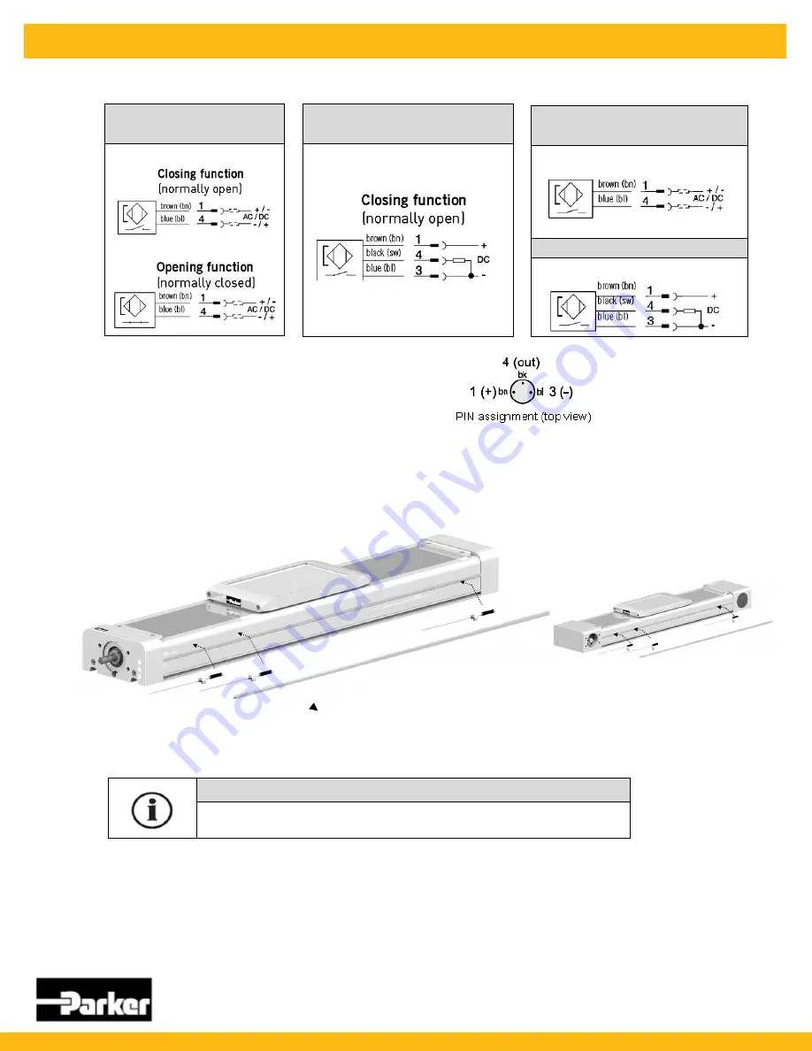
Magnetic Switch Types
7.5.3
Connection Assignment for M8 Connector
The connector assignment complies with DIN EN 50044
3
-
pin connector assignment
7.5.4
Setting up the External Magnetic Switches
Only possible with the IP54 cover!
Retrofitting:
All magnetic switches are mounted via a switch rail to be affixed onto the IP54 cover.
HMRB
Remove the
strip
from the IP54 cover.
Setting up the magnetic switches
Insert the previously aligned magnetic switches into the switch rail (size 1.5 Allen key).
Adjusting the switch points (setup)
Move the magnetic switches until the switch point is reached.
Tightly clamp the magnetic switch with a size 1.5 Allen key.
Connecting the magnetic switches
Connect the respective connection cable with the M8 connector for the magnetic switch.
Secure the loose cable in the T
-
slot with the cable holders.
Insert the connection cable in the controller
NOTE
Adjust the carriage to the desired position (end position / homing) and then move the
magnetic switch in the T
-
slot until the switch point is reached
Electrical connection:
Cable type RST
-
K
Reed 2
-
pole
Electrical connection:
Cable type EST
-
K
PNP 3
-
pole
Electrical connection:
Plug type RST
-
S
Reed 2
-
pole
Type EST
-
S
PNP 3
-
pole


