


14
WWW.PARKERMOTION.COM
PH: (724)
-
861
-
8200
HMR Series Positioners
7.2
Installation of Linear Drive
All installation measurements can be found under
“6.3
Carrier profile and drive body
”
and in the
HMR catalog.
►
During assembly, the HMR must be sufficiently supported and securely placed in a machine/system.
The maximum straightness and evenness in the running direction of the linear system can only be achieved if
the corresponding mounting points or surfaces are within the required tolerance.
The mounting surface for the profile version must have evenness of at least 0.2 mm/m at the clamping points.
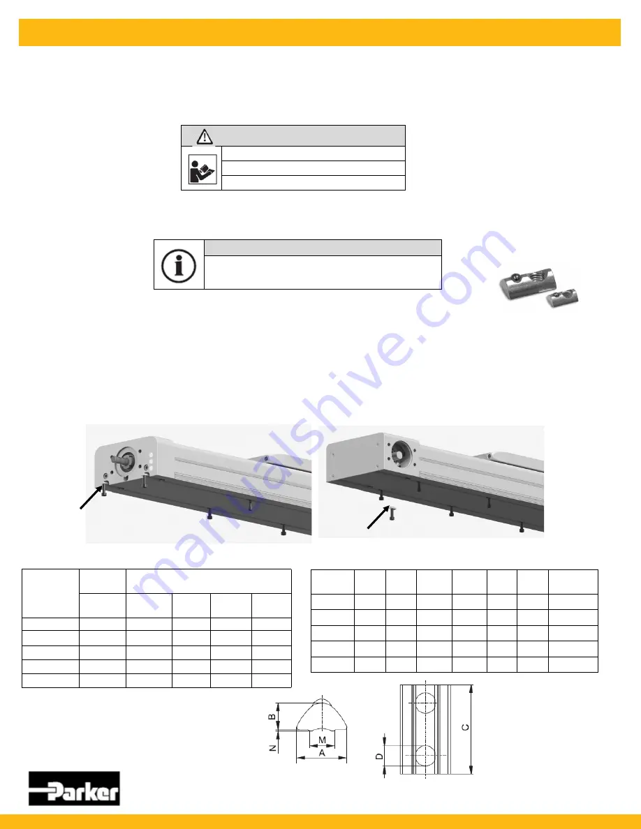
7.2.1
Mounting with T
-
slots
►
Use of T
-
slot profiles. Mounting from below.
Standard screws and sliding blocks or rails from the common profile systems can be used.
Mounting parts such as sliding blocks are available as accessories.
►
Please observe the required number of T
-
sliding blocks in accordance with the axial holding force for
secure assembly (see table below and HMR catalog.
ATTENTION
Straightness tolerance exceeded
The screw
-
on surface is important!
►
Ensure evenness and straightness
NOTE
►
Adhere to the tightening torques for screws according to
section 7.1.
HMRB
T
-
Slot mounting
T
-
Slot mounting
Max, axial holding force per mounting set
Product size
T
-
slot
Min, number of sets required per meter
N
horizontal
horiz,
side
over
head
vertical
HMRx08
1,000
4
11
19
5
HMRx11
1,000
4
11
19
5
HMRx15
1,600
4
5
10
5
HMRx18
2,700
4
5
10
5
HMRx24
3,200
4
4
8
5
Dimension table
-
T
-
slot mounting HMR
Product
A
B
C
ØD
M
N
Order no.
HMRx08
8.0
4.0
11.5
M5
5.0
0.5
56351FIL
HMRx11
8.0
4.0
11.5
M5
5.0
0.5
56351FIL
HMRx15
10.5
6.4
22.5
M6
6.4
0.6
56352FIL
HMRx18
13.5
6.7
22.5
M8
8.5
1.00
56353FIL
HMRx24
16.5
8.9
28.5
M10
10.5
1.00
56354FIL
HMRS


