Parker Hannifin Corporation
Instrumentation Valve Division
Jacksonville, Alabama
MI-106
2
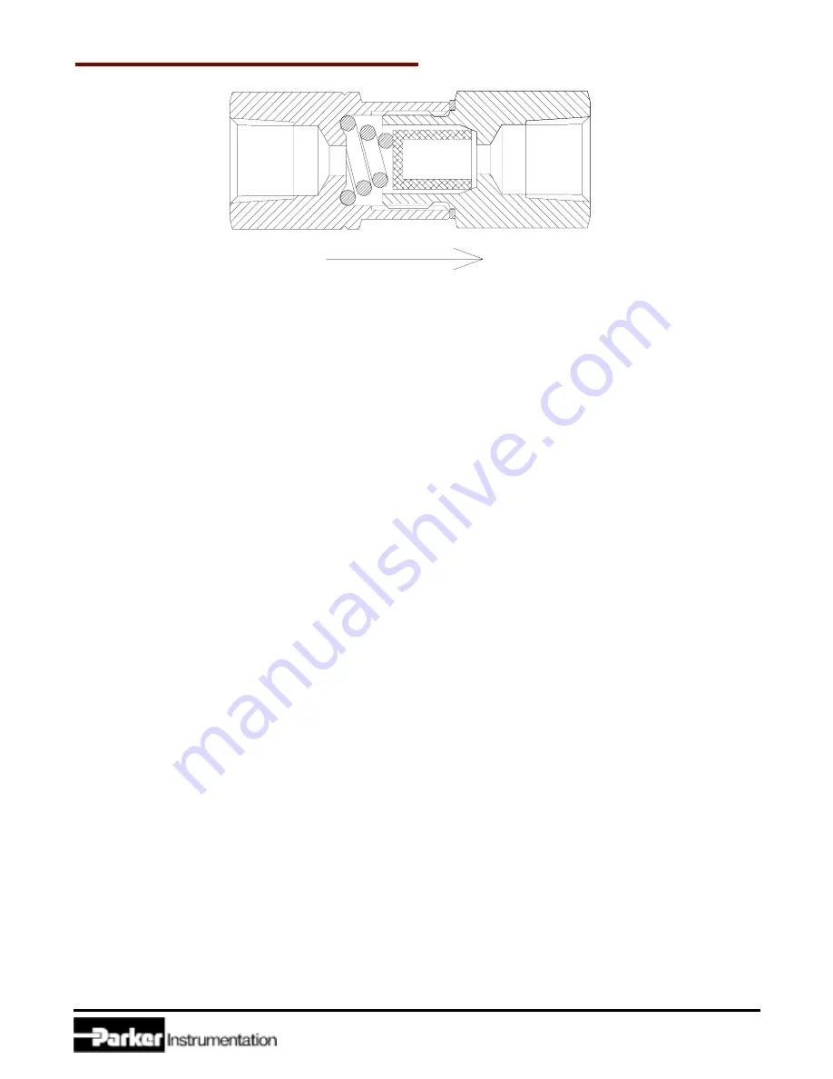
Figure 1: Inline Filter with Sintered Element Cross Sectional View
purchased prior to July 1, 1993
IMPORTANT NOTICE
To improve the Inline Filter, the components and assembly procedures were changed on July 1, 1993.
All Inline Filters assembled prior to July 1, 1993 should use Procedure A for disassembly and re-assembly. These can
be identified by an external gasket at the joint between the Cap and Body.
All Inline Filters assembled on or after July 1, 1993 should use Procedure B. These can be identified by the absence of
an external gasket at the joint between the Cap and Body.
F2 Series Inline Filters kits contain two style seats. Inspect your existing components to determine which style seat
should be used. Refer to Figure 7.
PROCEDURE A
WARNING: MAKE CERTAIN THE SYSTEM IN WHICH THE FILTER IS INSTALLED IS DRAINED AND/OR EX-
HAUSTED OF ALL PRESSURE BEFORE STARTING FILTER REMOVAL OR DISASSEMBLY, FAILURE TO DO SO
CAN CAUSE DEATH, PERSONAL INJURY AND PROPERTY DAMAGE.
1. Verify that the Inline Filter Maintenance Kit being used is appropriate for the Filters size, the filter micron rating, and
the service requirements. Always contact your authorized Parker representative if any questions arise.
2. Clamp the Inline Filter Body (next to the flow symbols arrow) at its hex-flats. Vertical orientation of the Inline Filter
in a vise for maintenance or repair (with flow arrow pointing DOWN) is recommended.
3. Loosen the Body from the Cap by turning counterclockwise with the following size hex wrench:
F2 Filters
5/8 inch
F4 Filters
3/4 inch
F6 Filters
1 inch
F8 Filters
1-1/4 inch
4. Remove the Gasket, Filter Element and the Spring. Discard each of these components.
REASSEMBLY
1. Make certain all parts are free of dirt or other contamination before starting reassemble of the Filter.
2. Apply a small amount of lubricant, as consistent with the Filters service requirements, on both sides of the new
Gasket. Always consult your authorized Parker representative if any questions arise.
3. Refer to Figures 1 and 2. Place the Gasket on the outer diameter face of the Body, to allow for the later assembly
of the Cap to the Body sub-assembly.
CAUTION:
The Gasket must be flush with the entire hex face before tightening.
4. Place the new Filter Element inside the Body. The new Filter Elements closed end must be face out.
5. Place the new Spring on top of the Filter. The Springs small diameter end must sit on the Filter.
6. Carefully install the Cap onto the Body Sub-Assembly by turning clockwise with the following size hex wrench to
the following specified torque:


