


12
Pilot Operated Proportional DC Valve
Series D*1FE
Operation Manual
Parker Hannifin Corporation
D_1FE 5715-688 UK CM 18.01.2019
5. Operating Instructions
Preferred Hydraulic Initial State
For valves with zero lap spools, distinction
must be made between hydraulic neutral
position and power-down position. Neutral
position is taken at neutral input signal, cor-
responding to zero position of the hydraulic
symbol. When the valve is switched off – no
supply voltage, no enable, current signal
(code S) < 3,8 mA – zero lap valves take the
power down position (approx. 10 % opening)
according to the ordering code. For valves with
overlap spools, neutral position and power
down position are the same (zero position).
Supply pressure must be ensured before valve
is energized.
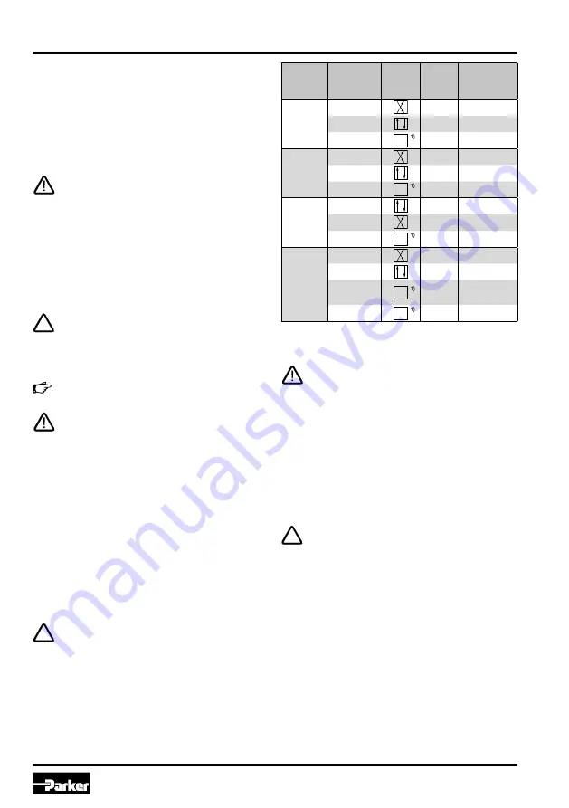
Code
command
signal
Command
signal
Function
VCD
actuator
Diagnostic
signal
B
0…+10 V
on
0…-10 V
0…-10 V
on
0…+10 V
Overload
off
ca. 12.5 V
E
0…+20 mA
on
0…-10 V
0…-20 mA
on
0…+10 V
Overload
off
ca. 12.5 V
K
0…+10 V
on
0…+10 V
0…-10 V
on
0…-10 V
Overload
off
ca. 12.5 V
S
4…12 mA
on
0…-10 V
12…20 mA
on
0…+10 V
0…3,6 mA
off
Cable break,
ca. 12.5 V
Overload
off
ca. 12.5 V
Enable input (only for Code 5 / 11+PE as well
as Code 7 / 6+PE)
A signal voltage enables the actuator drive of the
valve. Continuous operation of the valve requires a
permanent voltage 5...30 V (i.e. the supply voltage).
In case of disabling the signal the valve will reach its
power down position spring-actuated independently
from the command signal value.
The enable function represents no safety ar-
rangement against unwanted valve opera-tion
in terms of rules for accident prevention! To
block the valve function under all conditions,
more advanced steps are necessary, i.e. the
installation of additional safety check valves.
Command signal input
The spool stroke behaves proportional to the com-
mand signal amplitude.
The command input signal needs to be filtered
as well as free of inductive surges and modu-
lations. Due to the sensitivity of the valve a
high signal quality is recommended, this will
prevent malfunction.
Incorrect signal amplitude levels may disturb
the functionality and can damage the valve.
The option 4...20 mA uses the “3.6 mA“ condi-
tion as breakdown-information. This means
the presence of an evaluable failure informa-
tion if the input signal line is interrupted. In
this case the actuator drive will be switched
off. The drive will switch on when the input
signal reaches a value of 3.8 mA, it switches
off when the command falls below 3.6 mA.
This determination follows the NAMUR-
specification NE43.
NAMUR is an association of users of process
control technology.
Diagnostics output
A diagnostics signal is available. Its voltage repre-
sents the operating condition of the valve.
The output may drive a load of max. 5 mA.
Exceeding of this limit leads to malfunction.
1)
Diagnostic signal 12,5 V in error case. Spool
moves in a defined postion, please see order-
ing code „spool position at power down“.
Summary of Contents for D41FE
Page 20: ......