


Parker EME
Device description
192-120148N5 June 2011
37
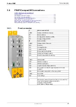
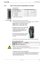
3.6.7.
Motor / motor brake Compax3M (axis controller)
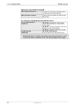
Connector X43
PIN
Designation
Motor cable lead designation*
BR-
Motor holding brake *
BK
5
Br2
BR+ Motor holding brake *
WH
4
Br1
PE
PE (motor)
YE / GN
YE / GN YE / GN
W
W (motor)
W / L3 / D / L-
3
U3
V
V (motor)
V / L2
2
U2
U
U (motor)
U / L1 / C / L+
1
U1
* depending on the cable type
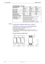
<80m per axis (the cable must not be rolled up!)
The entire length of the motor cable per axis combination may not exceed 300m.
A motor output filter is required for motor cables >20 m:
MDR01/04 (max. 6.3 A rated motor current)
MDR01/01 (max. 16 A rated motor current)
MDR01/02 (max. 30 A rated motor current)
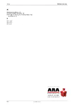
Shielding connection of the motor cable
The cable must be fully-screened and
connected to the Compax3 housing. Use the
cable clamps/shield connecting terminals
furnished with the device.
The shield of the cable must also be connected
with the motor housing. The fixing (via plug or
screw in the terminal box) depends on the
motor type.
Motor cables can be found in the accessories chapter of the device description.
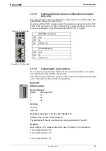
Motor holding brake output
Motor holding brake output
Compax3
Voltage range
21 – 27VDC
Maximum output current (short circuit
proof)
1.6A
Attention - Please wire the motor holding brake!
Connect the brake only on motors which have a holding brake! Otherwise make
no brake connections at all.
Requirements cables for motor holding brake
If a motor holding brake is present,
one cable
of the motor holding brake must be
fed on the device side through the toroidal core ferrite provided as accessory
ZBH0x/xx (63
Ω
@1MHz, di=5.1mm), in order to ensure error-free switching on
and off of the motor holding brake.
Compax3M motor
cable


