


Parker EME
Introduction
192-120148N5 June 2011
17
2.7.1.2
Conditions of utilization for cables / motor filter
Operation of the devices only with motor and feedback cables whose plugs
contain a special full surface area screening.
<80m per axis (the cable must not be rolled up!)
The entire length of the motor cable per axis combination may not exceed 300m.
A motor output filter is required for motor cables >20 m:
MDR01/04 (max. 6.3 A rated motor current)
MDR01/01 (max. 16 A rated motor current)
MDR01/02 (max. 30 A rated motor current)
Shielding connection of the motor cable
The cable must be fully-
screened and connected to the Compax3 housing. Use the
cable clamps/shield connecting terminals furnished with the device.
The shield of the cable must also be connected with the motor housing. The fixing
(via plug or screw in the terminal box) depends on the motor type.
< 80m
Corresponding to the specifications of the terminal clamp with a temperature range
of up to 60°C.
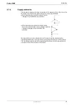
Signal lines and power lines should be installed as far apart as possible.
Signal lines should never pass close to excessive sources of interference
(motors, transformers, contactors etc.).
Do not place mains filter output cable parallel to the load cable.
2.7.1.3
Additional conditions of utilization
Operation with standard motors.
Use only with aligned cont
roller (to avoid control loop oscillation).
Connect the filter housing and the device to the cabinet frame, making sure that the
contact area is adequate and that the connection has low resistance and low
inductance.
Never mount the filter housing and the device on paint-coated surfaces!
Make sure to use only the accessories recommended by Parker
Connect all cable shields at both ends, ensuring large contact areas!
Motor and Feedback
cable:
Compax3M motor
cable
Compax3M encoder
cable:
Cable
Cable installation:
Motors:
Control:
Grounding:
Accessories:


