


Refrigerating Specialties Division
9
COMPENSATED TYPE INLET
PRESSURE REGULATORS
These pressure regulators modulate the inlet (evaporator) pressure in
accordance to load requirements as sensed by pneumatic or electric
thermostat or humidistat. When supplied with Range D, they also may
be used to control condensing pressures: for example, as part of a
Heat Reclaim system. In addition to standard versions described, these
regulators may be combined with any of the multi-function features by
using the modular construction. (See A4AS, A4AB and A4AD.)
A4AP PNEUMATICALLY COMPENSATED INLET
PRESSURE REGULATOR
The A4AP Pressure Regulator modulates the
inlet (evaporator or condenser) pressure in
response to a pneumatic signal applied on top
of the pilot diaphragm. The air must be clean,
dry and oil free. To avoid the possibility of
moisture from the compressed air freezing in
the bonnet or in other parts of the control
system, dehydrated air supply must be used
whenever it may come in contact with
temperatures below freezing.
Operation-A pneumatic thermostat-controller
modulates the air pressure applied to the top
of the diaphragm as the temperature at the
thermostat changes. Whether used as part of
a cooling system to control evaporator
pressure, or as part of a Heat Reclaim system to control condensing
pressure, a rise in temperature at the thermostat must cause a decrease
in controlled air pressure. The decrease in air pressure will lower the
regulator set-point and produce a lower inlet pressure and lower
evaporator or condenser temperature. Conversely, a drop in temperature
at the thermostat must cause an increase in air pressure, with a resultant
increase in evaporator or condenser temperature. Normally, the
controller modulates the air pressure from 3 to 15 psig throughout its
control range.
Adjustment-Adjust the controller according to manufacturer’s
instructions and set it for the desired sensitivity. This sensitivity setting
depends on the amount of regulator inlet pressure change necessary
to counteract the load change to keep the temperature at the thermostat
within the desired limits.
To adjust the pressure regulator, disconnect the air line and, following
the procedure described for A4A, adjust the regulator for the lowest
inlet pressure desired. This setting represents the lowest inlet pressure
the regulator will allow, thus providing a low limit feature to the regulator.
Connect the air line. From this point, the inlet pressure will be increased
1 psi for every 1 psi pressure increase the controller applies to the top
of the diaphragm. Note that the controller can only increase the inlet
pressure (regulator set-point) from the minimum regulator pressure
setting. Available in Ranges A, D and V.
A4A3P PNEUMATICALLY COMPENSATED
INLET PRESSURE REGULATOR
Operation-The A4A3P Pressure Regulator
operates like the A4AP Regulator except that
it uses a unique multiplier module to cause a
3 psi change in the inlet pressure for every
1 psi change in the air pressure the controller
applies to the top of the diaphragm. This
causes faster response and provides a
potential pressure rise above the low setting
3 times as great as the A4AP Regulator.
Example: 45 psi instead of 15 psi.
Adjustment - Same as the A4AP Regulator.
Available in Ranges A and V only.
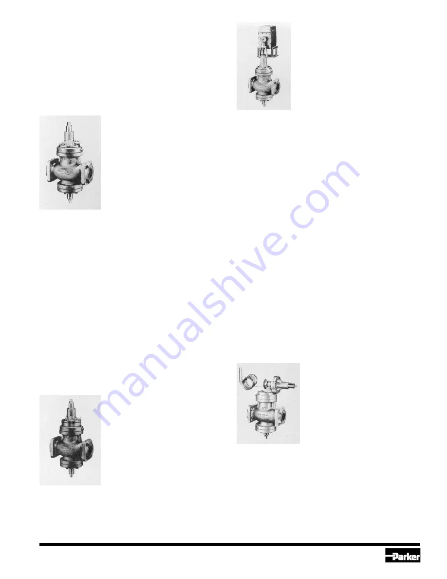
A4AM ELECTRICALLY COMPENSATED
INLET PRESSURE REGULATOR
The A4AM Pressure Regulator modulates the
inlet (evaporator) pressure in response to an
electric signal applied to a motor mounted on
the regulator pilot. When supplied with Range
D, they also may be used to control condensing
pressures. For example, as part of a Heat
Reclaim system. When the regulator is used in
a location where excessive moisture or corrosive
or explosive atmosphere exists, or in low
temperature applications where ice could
accumulate on the valve stem, the A4AMR with
remote pilot can be used. The cover should be
kept on the motor at all times to protect it from dust and mechanical
damage. No lubrication of the motor is needed.
Operation - The motor will respond to a signal from a suitable
potentiometer type of controller, for example, a thermostat. When the
temperature at the sensing element changes, the thermostat changes
the resistance in the electric circuit. The motor responds immediately
to the signal and rotates to rebalance the circuit. This rotation is
transmitted through a cam to the valve stem and range spring to change
the set-point by changing the spring pressure. Whether used as part of
a cooling system to control evaporator pressure, or as part of a Heat
Reclaim system to control condensing pressure, an increase in
temperature at the thermostat must decrease the spring pressure and
lower the inlet pressure and the evaporator or condenser temperature.
Normally, the cam rotation is 160° and one minute of time is required
for the full rotation. A motor with 240° cam rotation and 1.5 minutes
rotation time is available.
Adjustment - Adjust the controller sensitivity to the desired point
according to the manufacturer’s directions. Open the regulator manually
(manual opening stem backed out) and run the system until the
temperature at the sensing element reaches the desired level. Adjust
the controller (thermostat) setting to a reading which will cause the
cam of the motor to rotate and stop in center cam position. Put the
regulator back into automatic operation by turning the manual opening
stem in. Loosen the pressure adjusting screw lock nut and turn the
adjusting screw until the desired inlet pressure for this temperature
and load condition is reached. Turning the adjusting screw in will lower
the pressure, turning it out will raise the pressure. If after several hours
of operation the temperature is not as desired, re-adjust the pressure
adjusting screw slightly. Once the desired setting is reached, make
sure the lock nut is tightened. The valve will now modulate in response
to load variations to maintain constant temperature.
Available in Ranges A, V and D. Honeywell motor has 160° cam rotation
which is equivalent to a change in set-point of 4.2 bar (60 psi) for Ranges
A or V, or 7.5 bar (106 psi) for Range D; Penn motor has 240° cam
rotation which changes set-point 6.3 bar (90 psi) for Ranges A or V, or
11.2 bar (159 psi) for Range D.
A4AT DIRECT ACTING
TEMPERATURE REGULATOR
The A4AT Regulator modulates flow in
response to the temperature variation sensed
by its thermal bulb. A special temperature
pilot replaces the standard A4A pressure
pilot. A rise in temperature will cause the
valve to open; a drop will cause it to close.
This valve responds only to temperature
changes and is not a pressure regulator.
Operation - Temperature changes of the
cooled medium are sensed by the thermal
bulb of the pilot. As the bulb is warmed the charge in the thermal element
expands, creating an increase in pressure on the element diaphragm.
The resulting force pushes a push pin against the pilot diaphragm,
lifting it off the seat, allowing inlet pressure to reach the top of the
piston of the main regulator, causing the main valve to open. A drop in
the temperature at the thermal bulb causes the opposite to happen,
closing the main valve.
Adjustment - In addition to the pressure gauge at the inlet, a
thermometer is needed in the cooled medium. Set the regulator pilot to
the desired temperature by turning the adjusting stem. The temperature
scale is only approximate and minor adjustments will be necessary
after the system has been in operation for a while to obtain the desired
temperature setting. Standard Range is -30°C to +30°C (-20°F to 80°F).
Also available: 20°C to 60°C (60°F to 140°F). Maximum temperature to
which thermal bulb can be exposed is 65°C (150°F).


