Page 11 - 30
15.
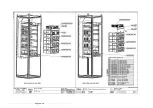
Populate rack with power and control modules. (*** denotes a power variant which must be
verified from the ratings table). Modules are pulled into place via the insertion/extraction
screws on the side of each module. This is a multi turn screw where both screws should be
turned simultaneously or alternatively no more than 2 turns on each side before returned to
the opposite screw. Use 5mm Allen T bars, screws will increase their resistance significantly
when the module is fully seated (
do not use more than 10Nm of torque
).
Refer to Configuration Table on page 23
for module Details.
Slide the CS module LA471171U*** (item
284) into the bottom slot.
Slide 3 CD modules LA471160U*** (item
283) into the next 3 slots.
When fitted, slide a CP module
LA471175U*** (item 282) into the top slot.
Summary of Contents for AC890PX Series
Page 1: ...User Mounting and Assembly Instructions HM501225U001 Issue 3...
Page 23: ...Page 23 30 LA501088U000_Page4...
Page 24: ...Page 24 30 LA501088U000_Page5...
Page 25: ...Page 25 30 LA501088U000_Page6...
Page 26: ...Page 26 30 LA501088U000_Page7...
Page 27: ...Page 27 30 LA501088U000_Page8...
Page 28: ...Page 28 30 HG501140...
Page 29: ...Page 29 30 HG501087...
Page 30: ...Page 30 30 HG501237U001...


