


4
Parker Hannifin Manufacturing Germany GmbH & Co. KG
Pump & Motor Division Europe
Chemnitz, Germany
Axial Piston Pump
Series PV, series 47 and higher
Bulletin MSG30-3245-INST/UK
Installation manual
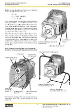
interface for
compensator
alternative drain
port L2
L1 drain port
pressure port
(outlet)
gage port,
ISO 6149-1;
M14x1.5
adjustment screw
lock nut
Port positions for PV (shown for clockwise
rotation, for ccw rotation ports are mirrored)
suction port
(inlet)
bearing flushing port, covered,
below pump
alternative drain port L3
case drain line from drain port
main flushing line to
alternative drain port 1, 2
bearing flushing line to
bearing flushing port L4
For side mounting (suction port facing down) use
alternative drain port 1 (cw rotation) or 2 (ccw
rotation).
Note:
During operation of PV pumps of all sizes
under the following conditions:
Q ~ Q
max
p
inlet
< 2 bar absolute
P
outlet
< 25 bar
(e.g. low pressure circulation) the drain flow can
change direction. Fluid is taken from the case
into the piston mainly through the decompression
orifice and across the slippers. There is a danger
that the pump case runs dry, the pump overheats
and the bearings lack of lubrication when the fluid
is removed from the pump case.
Therefore the drain pipe must be able to take
fluid from the reservoir. That means: The drain
line must end below fluid level, and a check valve
in the drain line is not permissible. If it has to be
installed for whatever reason the case needs to
be flushed with a flow of 10 – 15 % of the nominal
pump flow.