20
13
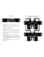
Linking up the Signal and Speakers in BRIDGE Mode
CAUTION!
Never attempt to jumper or otherwise link up any pins of output connectors.
To Speaker
To Input Signal Source
BRIDGE Mode
Input signal is linked up to Channel 1 input connector.
Speaker is linked up to Channel 1 output of with NL4FC SPEAKON.
MODE switch is set to BRIDGE.
Use channel 1 LEVEL control to adjust the level of the input signal (located on the front
panel).
(Only for input modules with a sensitivity switch or crossover)
For most applications, it is recommended to set the input HI PASS FILTER switches to
ON. In this mode, only the Channel 1 switch is enabled. However, when it is necessary to
obtain a liner frequency response to drive full-range speaker systems, as in studios or
cinema houses, set this input filter switch to OFF. See the Input Filter Section.
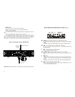
INPUT MODULE WITH SENSITIVITY SWITCH
(Option)
THROUGH
–
line outputs for Channel 2 & 1, respectively (XLR male).
Are used to deliver input signal along the respective channel to the input of another
amplifier.
THROUGH connectors are parallel to INPUT connectors of respective channels.
GAIN
–
input sensitivity switches for Channel 2 & 1, respectively.
Are used to select the input sensitivity (0.775V, 1.4V) or fixed gain (32 dB) for
respective channel.
INPUT
–
Channel 2 balanced input (XLR female).
Is used to supply input signal to channel 2.
HI PASS FILTER
–
cutoff filter switches for Channel 2 & 1, respectively.
Are used to enable/disable input high-pass filter of the respective channel (See: Input
Filter).
MODE
switch:
–
MONO
–
two channels drive two separate loads from a single input signal source;
–
STEREO
–
two channels drive two separate loads from two separate input signal
sources;
–
BRIDGE
–
two channels drive a common load from a single input signal source.
INPUT
–
Channel 1 balanced input (XLR female).
Is used to supply input signal to channel 1, channel 1 and 2 (in MONO mode), and a
common input signal (in BRIDGE mode).
MODE switch
is set to
BRIDGE


