21
12
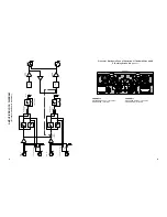
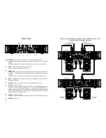
Linking up Signal and Speaker Systems in Case of Parallel Operation of Two
Amplifiers within a Full-Range Stereo Set
To Channel 1
Input Signal Source
To Channel 2
Input Signal Source
Channel 2 Speaker
Channel 1 Speaker
Amplifier 2
Amplifier 1
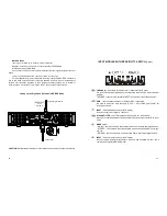
THROUGH
–
line outputs for Channel 2 & 1, respectively (XLR male).
Are used to deliver input signal along the respective channel to the input of another
amplifier.
THROUGH connectors are parallel to INPUT connectors of respective channels.
INPUT
–
Channel 2 balanced input (XLR female).
Is used to supply input signal to channel 2.
MODE
switch.
–
MONO
–
two channels drive two separate loads from a single input signal source;
–
STEREO
–
two channels drive two separate loads from two separate input signal
sources;
–
BRIDGE
–
two channels drive a common load from a single input signal source.
INPUT
–
balanced input (XLR female) for Channel 1 in STEREO; Channels1 and 2 in
MONO; BRIDGE mode.
MAINS IN
–
power cord socket for 23
0 V AC 50/60 Hz grounded mains.
OUTPUT
–
Channel 1 output.
Is used to connect a load (speaker system) to Channel 1 with a SPEAKON
®
connector,
as well as to connect a load (speaker system) to the amplifier in BRIDGE Mode. In
addition, Channel 2 output is linked to Channel 1 output socket thus making it possible
to connect the speaker systems of both channels to this output socket with a single
NL4FC connector (wired accordingly).
OUTPUT
–
Channel 2 output.
Is used to connect a load (speaker system) to Channel 2 with a SPEAKON
®
connector.
GROUND LIFT
switch.
REAR PANEL
Channel 2
Speaker
Channel 1
Speaker


