Chapter 7 - Maintenance
This chapter details the scheduled maintenance required by the T6M base station.
It also provides fault finding guidance.
SCHEDULED MAINTENANCE
Scheduled maintenance to the T6M base station involves the following checks:
(1)
Transmit power and frequency accuracy test. This check should be carried out annually.
(2)
Receiver sensitivity check. This check should be carried out annually.
(3)
Battery replacement (applicable only to base stations fitted with the internal battery option).
The life of the battery depends upon its usage; refer to ‘Battery Replacement’ on page 52.
Test Equipment Required
The test equipment necessary to complete the scheduled maintenance is listed in Table 8.
Table 8. List of test equipment
Item
Description
1
Through-line wattmeter.
2
20 dB attenuator (>15 W continuous power rating).
3
VHF Frequency counter.
4
RF signal generator.
5
AF wattmeter.
6
Test lead for connecting the base station to the AF wattmeter. [See next heading.]
Test Lead
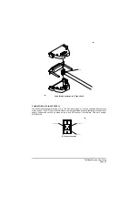
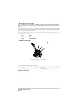
The test lead (Table 8, item 6) connects the base station to the AF wattmeter during receiver sensitivity
tests. The lead connections are detailed in Table 9.
Table 9. Test Lead Connections
7-Pin DIN Plug
(connects to base station's
Microphone connector)
AF Wattmeter Connector
Pin 5, receiver audio monitor
Input
Pin 7, earth
0 V
T6M Base Station User Guide
Page 49
Summary of Contents for T6M
Page 1: ...T6M Base Station User Guide Handbook Part Number 31 360T6MBS...
Page 12: ...Intentionally Blank T6M Base Station User Guide Page 12...
Page 16: ...Intentionally Blank T6M Base Station User Guide Page 16...
Page 48: ...Intentionally Blank T6M Base Station User Guide Page 48...
Page 56: ...Intentionally Blank T6M Base Station User Guide Page 56...
Page 58: ...Intentionally Blank T6M Base Station User Guide Page 58...
Page 59: ...BT6MBS 01 Front and Rear Layout Figure 1...
Page 60: ...BT6MBS 13 Rack Mounted Version Figure 2...
Page 62: ...BT6MBS 11 External Connection Diagram Figure 4...
Page 63: ...BT6MBS 10 Enclosure Securing Detail Figure 5...
Page 64: ...Base Station Block Diagram Figure 6 GA10547 Iss 3...
Page 65: ...Base Station Interconnection Diagram Figure 7 GA10548 Iss 3...
Page 66: ...Base Station Layout Diagram Figure 8 GA10719 Iss 1...
Page 69: ...Interface PCB Layout Diagram Figure 11 GA10751 Iss 1...
Page 70: ...BT6MBS 12 1 Cable Termination at the N Type Connector Figure 12...

