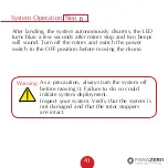
System Operation
39
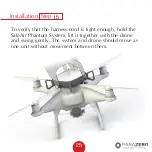
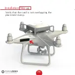
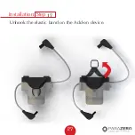
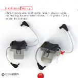
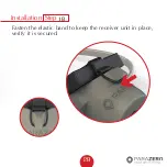
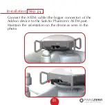
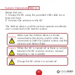
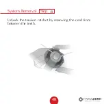
Step
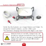
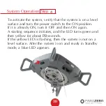
To activate the system, verify that the system is on a level
surface and turn the power switch to the ON position.
If it is already ON, turn it OFF and then ON again.
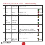
A starting sequence initiates, and the LED turns green and
then yellow for about 20 seconds.
If the yellow LED is flashing, then the system is not on a
level surface. After the system is on and ready in Standby
mode, a blue LED appears.
4
Summary of Contents for SAFEAIR Phantom ASTM
Page 1: ...Phantom Parachute Manual ASTM Version...
Page 8: ...8 SafeAir System Ports Switches LED USB C port System button Power switch ASTM port...
Page 12: ...12 Step Installation Remove the sticker cover from the placement stamp 3...
Page 17: ...17 Step Installation Remove the sticker cover from the Dual Lock placement stamp 8...
Page 22: ...22 Match plugs to sockets Installation...
Page 26: ...26 Step Installation Verify that the cord is not overlapping the placement stamp 16...
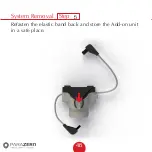
Page 27: ...27 Step Installation Unhook the elastic band on the Add on device 17...
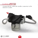
Page 30: ...30 Step Installation Connect the RC cable the smaller connector to the receiver s socket 20...
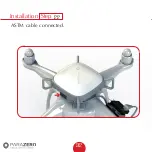
Page 32: ...32 Step Installation ASTM cable connected 22...
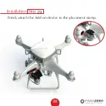
Page 33: ...33 Step Installation Firmly attach the Add on device to the placement stamp 23...
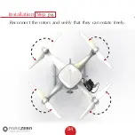
Page 34: ...34 Step Installation Reconnect the rotors and verify that they can rotate freely 24...
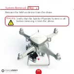
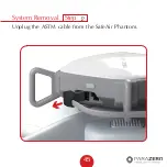
Page 45: ...System Removal 45 Step Unplug the ASTM cable from the SafeAir Phantom 2...
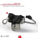
Page 46: ...System Removal 46 Step Unplug the RC cable from the receiver 3...
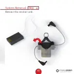
Page 47: ...System Removal 47 Step Remove the receiver unit 4...
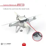
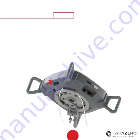
Page 50: ...System Removal 50 Step Unhook the cord from the metal hook 7...
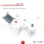
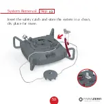
Page 51: ...System Removal 51 Step Remove the system from the drone 8...
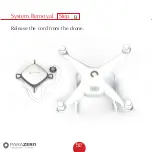
Page 52: ...System Removal 52 Step Release the cord from the drone 9...


