background image

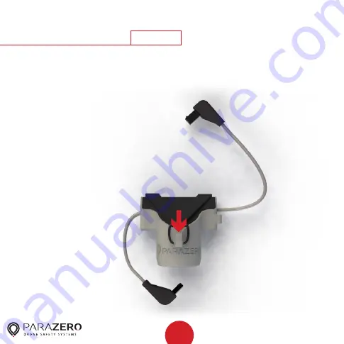
System Removal

48

Step

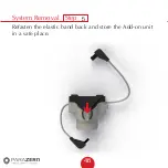
Refasten the elastic band back and store the Add-on unit 

in a safe place.

5

Summary of Contents for SAFEAIR Phantom ASTM

Page 1: ...Phantom Parachute Manual ASTM Version...

Page 2: ...of is not allowed except by the prior written authorization of ParaZero and then only to the extent authorized version 1 32 General Safety Instructions SafeAir System Package Content Professional Kit...

Page 3: ...r Phantom system is a smart parachute system that deploys autonomously after detecting a critical failure in your drone The parachute slows the descent rate of your drone and reduces the kinetic energ...

Page 4: ...r second 16 8 feet per second The Minimum Flight Altitude as defined by ASTM F3322 18 is 19 02 meters 62 4 feet Main Features Unique parachute deployment system that opens in a fraction of a second ev...

Page 5: ...ersion number is found on the product webpage parazero com phantom under the software tab A new device must be updated before first flight Warning Caution Do not move the drone or system while the sys...

Page 6: ...6 SafeAir System Package Content B Spring insert C Placement stamp E USB C cable D Placement tool A SafeAir Phantom System and connected safety catch...

Page 7: ...Professional Kit and RC System Package Content 5 Remote controller 8 Micro USB cable 6 Antenna 1 ASTM Add on 2 Dual Lock placement stamp 4 Placement for SafeAir Phantom only 3 DANGER stickers 7 Receiv...

Page 8: ...8 SafeAir System Ports Switches LED USB C port System button Power switch ASTM port...

Page 9: ...9 RC System Ports Switches LED Trigger switch Belt clip Lanyard hole Power switch Charging port...

Page 10: ...rds you and remove the rotors Unfold the placement tool so that the arms are fully extended with the battery side facing towards you Follow installation instructions carefully Systems that are not ins...

Page 11: ...11 Step Installation 1 Place the placement tool on the drone with the four circular holes around the four motors 2 Reconnect the four rotors in order to verify the placement tool s correct position 2...

Page 12: ...12 Step Installation Remove the sticker cover from the placement stamp 3...

Page 13: ...13 Step Installation Stick the placement stamp to the center of the drone by placing it carefully through the hole in the placement tool 4...

Page 14: ...14 Step Installation Remove the rotors and the placement tool and verify that the placement stamp is still securely in place 5...

Page 15: ...15 Step Installation Unbox your ASTM package and place it next to the drone together with the SafeAir Phantom 6...

Page 16: ...16 Step Installation Place the placement tool on the drone with the four circular holes around the four motors 7...

Page 17: ...17 Step Installation Remove the sticker cover from the Dual Lock placement stamp 8...

Page 18: ...old down the placement tool s flap onto the drone s arm and stick the placement stamp by placing it carefully through the gap in the flap Remove the placement tool and verify that the placement stamp...

Page 19: ...19 Step Installation Remove the safety catch from the bottom of the system and store it in a safe place for reuse during transport 10...

Page 20: ...tep Installation Place the harness cord around the landing gear of the drone with the SafeAir Phantom System placed upside down to the left of the drone while the string holder is adjacent to the dron...

Page 21: ...21 Step Installation Place the SafeAir Phantom System by matching the three plugs at the bottom of the system inside the corresponding sockets of the placement stamp See close up on the next page 12...

Page 22: ...22 Match plugs to sockets Installation...

Page 23: ...23 Step Installation 2 1 1 Slide the tension ratchet to the battery side of the drone 2 Lift the harness cord and hang it on the hook on the right side of the system 13...

Page 24: ...ckwise Make sure that the cord is being wrapped around the center of the ratchet Once the harness cord is firm lock it using 2 opposite teeth of the tension ratchet Throughout the whole tightening pro...

Page 25: ...lation To verify that the harness cord is tight enough hold the SafeAir Phantom System lift it together with the drone and swing gently The system and drone should move as one unit without movement be...

Page 26: ...26 Step Installation Verify that the cord is not overlapping the placement stamp 16...

Page 27: ...27 Step Installation Unhook the elastic band on the Add on device 17...

Page 28: ...28 Step Installation Place your receiver unit on the Add on device while maintaining the orientation shown in the photo Gently secure the antenna 18...

Page 29: ...29 Step Installation Fasten the elastic band to keep the receiver unit in place verify it is secured 19...

Page 30: ...30 Step Installation Connect the RC cable the smaller connector to the receiver s socket 20...

Page 31: ...31 Step Installation Connect the ASTM cable the bigger connector of the Add on device to the SafeAir Phantom s ASTM port Maintain the orientation on the drone as seen in the photo 21...

Page 32: ...32 Step Installation ASTM cable connected 22...

Page 33: ...33 Step Installation Firmly attach the Add on device to the placement stamp 23...

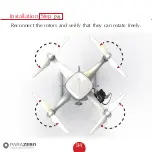
Page 34: ...34 Step Installation Reconnect the rotors and verify that they can rotate freely 24...

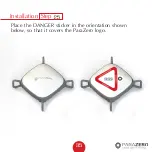
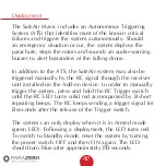
Page 35: ...35 Step Installation Place the DANGER sticker in the orientation shown below so that it covers the ParaZero logo 25...

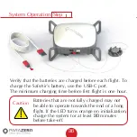
Page 36: ...eAir s battery use the USB C port The minimum charging time before first flight is one hour Caution Batteries that are not fully charged may not be able to operate towards the end of a long flight If...

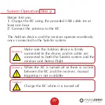
Page 37: ...erate seamlessly once connected to the SafeAir system Make sure the Add on device is firmly connected to the drone and its cable are connected to both the SafeAir system and the receiver unit before f...

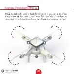
Page 38: ...stem Operation 38 Step Prior to takeoff verify that the system is placed firmly in the center of the drone and that the drone s propellers can spin freely without touching the flight termination rings...

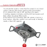
Page 39: ...r switch to the ON position If it is already ON turn it OFF and then ON again A starting sequence initiates and the LED turns green and then yellow for about 20 seconds If the yellow LED is flashing t...

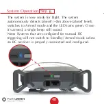
Page 40: ...detects takeoff 3m above takeoff level switches to Armed mode and the LED turns green Once it s armed a single beep will sound Note Systems that are configured for manual RC triggering will not switch...

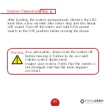
Page 41: ...o beeps will sound Turn off the rotors and switch the power switch to the OFF position before moving the drone Warning As a precaution always turn the system off before moving it Failure to do so coul...

Page 42: ...iggered manually by the RC signal through the receiver unit installed on the Add on device In order to manually trigger the system press and hold the RC Trigger switch until the RC LED turns solid red...

Page 43: ...Phantom System withstands significant force during deployment Systems that have been deployed five times must not be repacked and reused and should be replaced Repacking Caution For professional Safe...

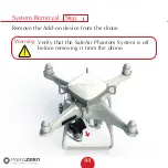
Page 44: ...System Removal 44 Step Remove the Add on device from the drone Warning Verify that the SafeAir Phantom System is off before removing it from the drone 1...

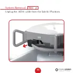
Page 45: ...System Removal 45 Step Unplug the ASTM cable from the SafeAir Phantom 2...

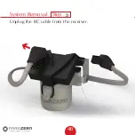
Page 46: ...System Removal 46 Step Unplug the RC cable from the receiver 3...

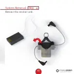
Page 47: ...System Removal 47 Step Remove the receiver unit 4...

Page 48: ...System Removal 48 Step Refasten the elastic band back and store the Add on unit in a safe place 5...

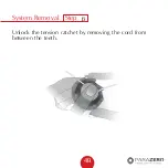
Page 49: ...System Removal 49 Step Unlock the tension ratchet by removing the cord from between the teeth 6...

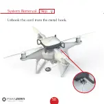
Page 50: ...System Removal 50 Step Unhook the cord from the metal hook 7...

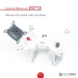
Page 51: ...System Removal 51 Step Remove the system from the drone 8...

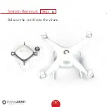
Page 52: ...System Removal 52 Step Release the cord from the drone 9...

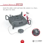
Page 53: ...System Removal 53 Step Insert the safety catch and store the system in a clean dry place for reuse 10...

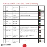
Page 54: ...urn the power switch to the OFF position and follow the repacking instructions 8 Flashing Red Low battery A one hour charge gives an hour of flight time The red flashing LED may be accompanied by othe...

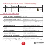
Page 55: ...ea Level 6000 meters 19 700 feet Maximum Speed 72 kilometers per hour 43 5 miles per hour Maximum Wind Speed 10 meters per second 19 5 knots Weight 200 grams 0 44 lbs Average Descent Rate 5 12 meters...

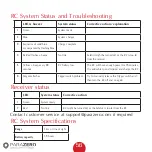
Page 56: ...ave enough power for 15 minutes It is advisable to end mission and charge the RC 6 Magenta flashes Trigger switch problem Try to manually release the Trigger switch and then turn the RC off and on aga...

Page 57: ...n radiate radio frequency energy and if not installed and used in accordance with the instructions may cause harmful interference to radio communications However there is no guarantee that interferenc...

Reviews: