background image

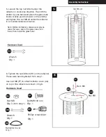
3. Install reflector to support with M8 screws 
(Qty. 6) 

4. Wrap the ceramic rope with clips (RR) 
around the top and bottom of the Ruby 
Quartz Glass Tube (E) and attach clips to 
glass. (fig 4-A)

Then place the Glass tube with both pieces of 
ceramic rope into glass tube holder at bottom. 
(fig. 4-B)

Assembly Instructions

3

4-B

4-A

ASSEMBLY INSTRUCTIONS

Hardware Used

Hardware Used

Wrench Qty 1

RR

E

Summary of Contents for OH-M744B

Page 1: ...ANSI 83 26 2014 CSA 2 37 2014 5016039 Round Flame Tower Heater OH M744S Stainless Steel OH M744B Heritage Bronze OH M744BL Hammered Blacak ...

Page 2: ...y persons who can understand and follow the instructions should use or service this heater EXPLOSION FIRE HAZARD Keep solid combustibles such as building materials paper or cardboard a safe distance away from the heater as recommended by the instructions Provide adequate clearances around air openings into the combustion chamber Never use the heater in spaces which do or may contain volatile or ai...

Page 3: ...a immediately Never install or remove the propane cylinder This heater is red hot during use and can ignite flammables that are too close to the burner Keep flammables at least 3 feet from sides 3 feet from top Keep gasoline and other flammable liquids and vapors well away from heater Store the propane cylinder outdoors in a well ventilated space out of reach of children Never store the propane cy...

Page 4: ...or protective device removed for servicing the appliance prior to placing back in service Installation and repair should be done by a qualified service person The heater should be inspected before use and annually by a qualified service person More frequent cleaning may be required as necessary It is imperative that the control compartment burners and circulating air passageway of the appliance be...

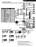
Page 5: ... L Base Plate 1 Parts List AAAlkaline Battery Qty 1 QQ Teflon Tape Qty 1 TT MM Screw M8 x 15 mm Qty 16 DD Wrench Qty 1 OO Bolt M8 x 15mm Qty 2 EE Nut M8 Qty 11 HH PP Philips screwdriver Qty 1 RR Ceramic Rope with Attachment Clips Qty 2 FF Screw M8 x 30 mm Qty 1 Screw M8 x 10 mm Qty 12 ADDITIONAL REQUIRED HARDWARE Adjustable opening wrench 2 20 cm 8 long Slip joint pliers 23 cm 9 long Philips screw...

Page 6: ...ewing 4pcs M5x10mm as show in fig 2 Nut M8 Qty 6 Already assembled Nut M8 Qty 3 Wrench Qty 1 Assembly Instructions 1 B 1 A 2 MM HH ASSEMBLY INSTRUCTIONS Hardware Used Hardware Used Before beginning assembly of product make sure all parts are present Compare parts with package contents list and hardware contents above If any part is missing or damaged do not attempt to assemble the product Contact ...

Page 7: ...around the top and bottom of the Ruby Quartz Glass Tube E and attach clips to glass fig 4 A Then place the Glass tube with both pieces of ceramic rope into glass tube holder at bottom fig 4 B Assembly Instructions 3 4 B 4 A ASSEMBLY INSTRUCTIONS Hardware Used Hardware Used Wrench Qty 1 RR E ...

Page 8: ... press the lower seat of the glass tube let it loose then install the glass tube 5 Loosen the top nut M8 x3 under the reflector in clockwise direction Then lift the emitter by one hand and place the glass tube inside Gently pull downward on the emitter and tighten the nut M8 x3 under the reflector in a counterclockwise direction 6 Tighten the nuts M8 x3 HH on the reflector These were hand tightene...

Page 9: ...x15 screws through the designated 90 degree metal brackets with a philips screwdriver Note These 4 metal brackets are included with the hardware and must be installed into the back panel using the M1x12mm screws Hardware Used DD x 5 x 1 PP Philips screwdriver Screw M8 15 mm Hardware Used DD x 5 x 1 PP Philips screwdriver Screw M8 15 mm 7 philips screwdriver designated 90 degree metal brackets with...

Page 10: ...n connect gas hose H fig 10 B The knob on the LP tank must be closed Make sure that the knob is turned clockwise to a full stop The cylinder supply sysem must be arranged for vapor withdrawl Check that the control knob on the control unit is turned off Hold old the regulator in one hand and insert the nipple into the valve outlet Be sure the nipple is centered in the valve outlet The coupling nut ...

Page 11: ...en corrected WARNING Do not smoke while performing this test and remove all sources of ignition WARNING A leak test must be performed annually and each time a cylinder is hooked up or if a part of the gas system is replaced and whenever any gas components are being replaced or serviced WARNING Never use an open flame to check for gas leaks Be certain no sparks or open flames are in the area while ...

Page 12: ...The installation must conform with local codes or in 12 13 WARNING After the cylinder is placed inside the heater secure the cylinder with block belt tightly 13 Install wheel kit to base plate by inserting 2 x Bolt M8 x 15mm through the wheel kit and base plate and securing them with 2 x Nut M8 use supplied wrench to tighten Hardware Used Wrench Qty 1 OO Bolt M8 x 15mm Qty 2 EE Nut M8 Qty 2 HH ...

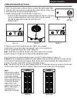
Page 13: ...stand all General Safety Information OPERATION INSTRUCTIONS DANGER 5 21 0212 5 RU RXWGRRU XVH RQO 1HYHU XVH LQVLGH KRXVH RU RWKHU XQYHQWLODWHG RU HQFORVHG DUHDV 7KLV KHDWHU FRQVXPHV DLU R JHQ R QRW XVH LQ XQYHQWLODWHG RU HQFORVHG DUHDV WR DYRLG HQGDQJHULQJ RXU OLIH Figure 1 JQLWHU 9DULDEOH FRQWURO NQRE Figure 2 gas lines before proceeding Note For initial start or after any cylinder change hold co...

Page 14: ...eliminate excessive noise from the burner turn the control knob to the PILOT position Then turn the knob to the level of heat desired Figure 3 Figure 4 Figure 5 Igniter Variable control knob Normal Abnormal Repeat step 6 through the glass tube to light the pilot Figure 4 As you are depressing the control knob place long stem lighter Push in control knob and turn counterclockwise to PILOT Figure 3 ...

Page 15: ...below 10 mph 6 Unit will operate at reduced efficiency below 40 F 7 Heater is outdoors outside any enclosure 8 There is adequate fresh air ventilation WARNING FOR YOUR SAFETY Be careful when attempting to manually ignite this heater Holding in the control knob for more than 20 seconds before igniting the gas will cause a ball of flame upon ignition WARNING FOR YOUR SAFETY Heater will be hot after ...

Page 16: ...ce of your heater Apply to exterior surfaces from the pole down Do not apply to emitter screen or domes Storage Between uses Turn Control Knob OFF Disconnect LP cylinder Store heater upright in an area sheltered from direct contact with inclement weather such as rain sleet hail snow dust and debris If desired cover heater to protect exterior surfaces and to help prevent build up in air passages No...

Page 17: ... Debris around pilot Clean dirty area Loose connections Tighten connections Thermocouple bad Replace thermocouple Gas leak in line Check connections Lack of fuel pressure Tank near empty Refill LPG tank Burner will not light Pressure is low Tank near empty Refill LPG tank Opening blocked Remove and clean Control not ON Turn valve to ON Thermocouple bad Replace thermocouple Pilot light assembly bent ...

Page 18: ...5016039 ...
Reviews: