background image

96

2 0 0 0 - A 2 - G B 2 3 - 0 0

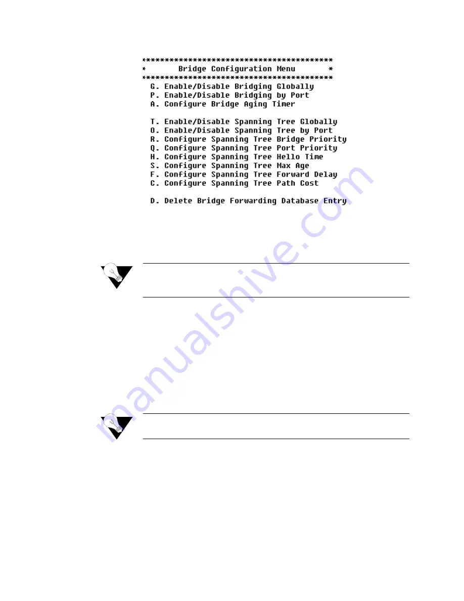
Figure 4.61

Bridge Configuration Menu 

You may sign on as Supervisor or Network Manager to configure the IAD as 
a bridge. Options that display in the Bridge Configuration menu are the same 
for both security levels.

NOTICE: 

Be sure to reset the IAD when you have finished making changes to 
Bridge configuration. Resetting the IAD causes the configuration 
changes to take effect.

Enabling and Disabling Bridging

For bridging to function correctly, you must enable bridging by port and then 
set the bridge aging timer. At least two ports must be enabled for bridging to 
function. You must also disable RIP poisoned reverse. The order in which you 
perform the procedures is irrelevant.
To enable routing globally, you must disable bridging globally. However, you 
may enable routing on some ports and bridging on others, depending on your 
requirements.

NOTICE: 

When bridging is disabled globally or on an interface (port) or an IP 
address is unconfigured, IP Over Bridge is disabled automatically.

IP Over Bridging

IP Over Bridging is intended for use when the IAD is in full bridged mode, 
and remote access (Telnet) and/or user authentication (RADIUS) are required. 
To implement IP Over Bridging, enable bridging globally and by port (as 
described in the paragraphs below) on the WAN connection (at least one 
DLCI/PVC must be configured), and assign an IP address to the WAN 
interface. When these conditions have been met (either in Routing or Bridging 
configuration), the IAD will prompt you to enable or disable IP Over 
Bridging. When the IP address is unconfigured, IP Over Bridging is disabled 

Summary of Contents for JetFusion 2100 Series

Page 1: ...JetFusion Integrated Access Device 2000 2100 2200 2300 Series User s Guide Document No 2000 A2 GB23 00 September 2004 ...

Page 2: ...documentation training distributor locations or Paradyne worldwide office locations use one of the following methods Internet Visit the Paradyne World Wide Web site at www paradyne com Be sure to register your warranty at www paradyne com warranty Telephone Call our automated system to receive current information by fax or to speak with a company representative Within the U S A call 1 800 870 2221...

Page 3: ...nly with a certified Class 2 power supply See Appendix C Specifications WARNING Changes or modifications to this unit not expressly approved by the party responsible for compliance could void the user s authority to operate the equipment The 2x08 complies with Part 68 of the FCC Rules and the requirements adopted by the ACTA On the bottom of the 2x08 unit is a label that contains among other infor...

Page 4: ...of this equipment in a residential area is likely to cause harmful interference in which case the user is required to correct the interference at the user s own expense This equipment generates uses and can radiate radio frequency energy and if not installed and used in accordance with the instruction manual may cause harmful interference to radio com munications However there is no guarantee that...

Page 5: ...ut in the Radio Interference Regulations of the Canadian Department of Commu nications Le présent appareil numérique n émet pas de bruits radioélectriques dépassant les limites appli cables aux appareils numériques de la class A prescrites dans le Règlement sur le brouillage radioélectrique edicté par le ministère des Communications du Canada 2216 2224s 2316s 2324s 2112s 2116s 2124s FCC Requiremen...

Page 6: ...e notice is not practical you will be notified as soon as possible You will be informed of your right to file a complaint with the FCC 4 Your telephone company may make changes to its facilities equipment operations or procedures that could affect the proper functioning of your equipment If they do you will be notified in advance so you can have the opportunity to maintain uninterrupted telephone ...

Page 7: ...u are using consult your dealer or local power company Do not allow anything to rest on the power cord Do not locate this product where the cord interferes with the free movement of people Do not overload wall outlets and extension cords as this can result in fire or electric shock Never push objects of any kind into the unit They may touch dangerous voltage points or short out parts that could re...

Page 8: ...vi 2 0 0 0 A 2 G B 2 3 0 0 ...

Page 9: ... Architecture 6 High POTS Port Features 6 High POTS Port Front Panel LED Status Indicators 7 High POTS Port Rear Panel Connectors 8 Chapter 2 Quick Start Guide Unpacking the IAD 11 Installing the IAD 12 AC Power and Uninterruptible Power Supply 12 Clearance Requirements 12 Wiring Requirements 12 Connecting the IAD Via a Terminal Emulator 12 Connecting the IAD to a PC 13 Logging in via a Terminal E...

Page 10: ...sable SNMP Traps via EOC 31 Configure Restart Trap Maximum Delay 31 Defining Different SNMP Version 3 Categories 31 LAN Configuration Menu 33 Establishing LAN Speed and Duplex Mode 33 Upgrading the System 34 Using TFTP Servers via LAN or WAN 34 Copying the Source Files 34 Upgrading via TFTP 34 Verifying the Upgrade 35 Utilities Menu 35 Ping Utility 36 Trace Route 37 Configure Console Baud Rate 37 ...

Page 11: ...ace USI 63 Configure Datalink Protocol 64 Configure ATM PVCs 66 Configure ATM Options 71 Configure DLCIs 73 Configure Frame Relay Options 76 Router Configuration 79 Basic Router Setup Tasks 80 Router Configuration Menu 81 Configure Port IP Address 82 Unconfigure Port IP Address 83 Configure Port Maximum Transmission Unit MTU 84 Add Remove a Static Route 84 Configure RIP Version by Port 86 Configur...

Page 12: ...cs 106 Set Jitter Delay 118 Voice Port Settings 118 Display Compander Mode µ law A law 123 Set Country Mode 123 Set DuSLIC Mode 123 Interworking Connections 124 FRF 5 125 FRF 8 126 Firewall Configuration 127 Creating a Firewall via IP Filtering and NAT 127 DHCP Server Configuration 128 Basic DHCP Server Setup Tasks 128 DHCP Server Configuration Menu 128 Enable Disable DHCP Server 129 Enable Disabl...

Page 13: ...try 146 Delete NAT Alias Entry 147 Setting PPP Options 147 Setting Derived Timing Options 147 Derived Timing Menu 147 Enable Disable Derived Timing 148 Chapter 5 Reports Reports Menu 149 Current Configuration Report 150 Network Statistics Reports 152 ICMP Statistics Report 153 IGMP Statistics Report 154 IP Statistics Report 156 PIM Statistics Report 157 TCP Statistics Report 158 UDP Statistics Rep...

Page 14: ...splay System Memory Statistics 181 Display Kernel Tasks Memory Statistics 182 Zero All Statistics 182 Chapter 6 Command Line Interface Introduction 183 CLI Help 183 Chapter 7 Troubleshooting and Diagnostics Using the Diagnostics Menu 197 POTS Diagnostics 198 Dialup Test 198 Hotline Test 199 Ring Test 199 Ring Test 199 On Off Hook Test 200 SDSL Diagnostics 201 Troubleshooting the IAD 201 Chapter 8 ...

Page 15: ...Pin Assignments 216 Console Port Pin Assignments DB 9 216 POTS Port Pin Assignments RJ11 216 10 100Base T Connector Pin Assignments RJ45 216 T1 E1 Connector Pin Assignments RJ48 216 T1 E1 2216s and 2224s 217 Voice Features 217 Analog Voice 217 Digital Voice 217 Data Features 217 WAN Features 218 Network Interfaces 218 T1 218 E1 218 T1 E1 Provisioning 219 ATM 219 Frame Relay 219 Universal Serial In...

Page 16: ...sory Port 226 Upgrades 226 Management 226 Security Features 226 Integrated Firewall 226 Management Interfaces 226 Alarms 226 Environmental 226 Connector Pin Assignments 228 Console Port Pin Assignments DB 9 228 POTS Port Pin Assignments RJ11 228 10 100Base T Connector Pin Assignments RJ45 228 SDSL Connector Pin Assignments RJ11 228 SDSL 2316s and 2324s 229 Voice Features 229 Analog Voice 229 Digit...

Page 17: ...7 Security Features 237 Integrated Firewall 237 Management Interfaces 237 Alarms 237 Environmental 237 Connector Pin Assignments 238 Console Port Pin Assignments DB 9 238 SHDSL Connector Pin Assignments RJ45 238 10 100Base T Connector Pin Assignments RJ48 238 ADSL Pin Assignments RJ11 238 SHDSL 2104 2104s and 2108 2108s 239 Voice Features 239 Analog Voice 239 Digital Voice 239 Data Features 239 WA...

Page 18: ... 245 Connector Pin Assignments 247 Console Port Pin Assignments DB 9 247 POTS Port Pin Assignments RJ21 247 10 100Base T Connector Pin Assignments RJ45 247 SHDSL Connector Pin Assignments RJ11 247 USI Connector Pin Assignments RS 530 V 35 248 Appendix C Application Notes Frame Relay 249 Setting the Fragment Maximum Frame Size 249 Peak Cell Rate PCR Considerations and Recommendations 250 Voice only...

Page 19: ...xxiii IP Packet Filtering Syntax and Grammar 255 Grammar 255 Filter Rules 256 Actions 256 Options 257 Matching Parameters 257 Keep History 259 Examples 260 Dial Plan 260 Appendix D Glossary ...

Page 20: ...xxiv 2 0 0 0 A 2 G B 2 3 0 0 ...

Page 21: ...mation Appendices are designed to complement the main chapters Chapter 1 Introduction introduces the features of the 2000 Series IADs including the hardware indicators and ports Chapter 2 Quick Start Guide describes the process of getting an IAD up and running in a typical customer premises This chapter is helpful if you re new to 2000 Series products because it lists each step beginning with unpa...

Page 22: ...llustrating its navigation and organization Appendix B Specifications defines the specifications for the 2000 Series IADs In addition this section provides ordering information and all the connector pin assignments for the interfaces on the back of the 2000 Series IADs Appendix C Application Notes provides various applications details Appendix D Glossary provides a glossary of terms used in this m...

Page 23: ...ge the power of wide area communications for competitive advantage In particular these new services allow SMBs often lacking the resources to install and manage multiple communications devices to compete effectively with their larger counterparts in the global marketplace The 2000 Series IADs are access devices that terminate a network WAN and provide the end user with the ability to send and rece...

Page 24: ...housed in a plastic enclosure with an external power supply All units are based on a common core design consisting of a Motorola Power QUICC CPU 16 or 8 Mbytes of dynamic memory and 2 Mbytes of FLASH memory Voice packetization and processing are handled by Texas Instruments Digital Signal Processors DSP Low POTS Port Features The Low POTS Port IADs provide a highly interoperable cost effective voi...

Page 25: ...8 2308 2304 2008 2004 and 2108 2104 IADs are listed in Appendix B Specifications Low POTS Port Front Panel LED Status Indicators The Low POTS Port front panels contain five LED status indicators Each is described in the table below Figure 1 1 Low POTS Port Front Panel LED Description POWER Illuminates when the IAD is powered on LAN LINK Illuminates when there is an operational LAN connection on th...

Page 26: ...N LIFE LINE LINE 1 8 telephone connectors and PWR Each of these connectors is described below Each unit has a Ground the use of which is illustrated in Figure 2 1 Typical Grounding Diagram Figure 1 2 T1 E1 Low POTS Port Rear Panel Connectors Figure 1 3 SDSL Low POTS Port Rear Panel Connectors Figure 1 4 ADSL Low POTS Port Rear Panel Connectors ...

Page 27: ... to a telephone line when there is no power or voice gateway to the IAD NOTICE The 2008 also uses the WAN connection for the Life Line connection WAN Connects through WAN interface as follows 2208 T1 E1 uses an RJ48 connector 2308 2304 SDSL uses an RJ11 connector 2008 2004 ADSL uses an RJ11 connector 2108 2104 SHDSL uses an RJ11 connector Data Interfaces The data connection through the IAD support...

Page 28: ...d dynamically allocate bandwidth between voice and data services Features include the following For SDSL supports the following DSLAMs ATM Lucent Nortel and Nokia Frame Relay AccessLan CopperMountain and Paradyne For SHDSL supports the following DSLAMS for ATM Lucent Nortel and Nokia Supports the following Voice Gateways CopperCom JetStream TdSoft Broadsoft MetaSwitch Cirpack NuERA Tollbridge Nort...

Page 29: ...LED Description POWER Illuminates when the IAD is powered on LAN LINK Illuminates when there is an operational LAN connection on the Ethernet port LAN Activity Flashes when there is activity on the Ethernet port WAN Link Flashes as the IAD is establishing a link and illuminates solid when there is a proper connection on the WAN port and synchronization has been achieved VOICE Illuminates when ther...

Page 30: ...h Ethernet cable or directly to a PC for accessing via Telnet using a cross over customer supplied cable The data interfaces connect through the IAD supporting IEEE 802 1 compliant bridging and routing When configured for routing supports Routing Information Protocol RIP version 1 version 2 or static IP routing The IAD complies with RFC 1812 when interfacing with IPV4 routers The IAD can terminate...

Page 31: ... cables Battery Backup Connects a battery backup accessory future feature Voice Lines Supports 12 16 or 24 analog telephones via RJ21 connectors LIFE LINE Provides access to a telephone line when there is no power or voice gateway to the IAD AC Power Input Connects the IAD to any AC 100 240 V outlet Data Interfaces The data connection through the IAD supports IEEE 802 1 compliant bridging and rout...

Page 32: ...10 2 0 0 0 A 2 G B 2 3 0 0 ...

Page 33: ...acking the IAD Each IAD is packed and shipped in a durable container Unpack and carefully remove the IAD from the package and packing material IAD Package Components Each IAD is shipped with the components listed below As you unpack them note their condition and identity and compare the list with the packing list in the package AC power adapter and cord 6 feet long or AC power cord Agency Complian...

Page 34: ...you install the IAD horizontally make sure you maintain at least 2 inches of horizontal distance from other IADs or other electronic equipment to ensure adequate ventilation and heat dissipation NOTICE Due to generated heat 2000 Series IADs should not be stacked on top of each other Wiring Requirements Make sure the telephone wiring LAN and WAN cables reach the IAD and can be dressed in a manner t...

Page 35: ...ail below NOTICE Ensure the IAD and PC are both powered OFF before connecting the console cable If both devices are not turned off when you connect the cables you may place the IAD in an unstable state and you may need to reset one or both devices before you can perform configuration tasks Connecting the IAD to a PC To connect the IAD to a PC via the console port follow the steps below 1 Turn off ...

Page 36: ...e Ethernet side NOTICE For Ground Start applications all elements in the voice path must be set to Ground Start NOTICE As the IAD boots it sends status messages to the console port If you are connected you will see the boot sequence progress NOTICE This unit should be installed by qualified service personnel only and must be connected to a socket outlet with protective earthing connection Logging ...

Page 37: ...administrative tasks Follow these procedures after performing the basic set up functions described in this Quick Start Guide 6 The IAD displays the password message Enter Password 7 Type the default password supervisor or your password if different and press Enter If login is not successful the IAD displays the following message Invalid UserID or Password Try again Press any key to continue 8 Pres...

Page 38: ...for input the current value is displayed in parentheses To conveniently accept the current value just press Enter Setting the Ethernet Port IP Address Before you configure the Ethernet IP address you should know the IP address and subnet mask that are to be assigned to this port They may be displayed on the work order or you may obtain or determine the appropriate IP address by consulting with the...

Page 39: ...terfaces that display depend on the specific IAD as shown in Figure 2 4 and Figure 2 5 below Figure 2 4 2308 Available Interfaces Figure 2 5 2208 Available Interfaces 3 Type 2 to set the IP address for the Ethernet port If the IP address is configured for the port the IAD displays information about the interface and a prompt such as that shown in the example below ...

Page 40: ...ation tasks Connecting via Telnet on page 2 19 this is a good time to disconnect the serial cable from the PC and IAD Setting the WAN Port IP Address To set the WAN port IP address follow the same procedures as those listed in Setting the Ethernet Port IP Address on page 2 16 Resetting the IAD Many configuration tasks require that you reset or restart the IAD before the new settings or configurati...

Page 41: ...the RADIUS server or the connection to the RADIUS Client goes down Telnet access will not be permitted Running Telnet Before you use Telnet to log into the IAD ensure the IAD and your PC are connected to the same network via straight through Ethernet cables or directly connected via a cross over cable and you know the IP address of the IAD Both devices must be on the same subnet To log in follow t...

Page 42: ...ommands see Appendix Entering Settings and Values When the IAD requests input for a setting or configuration value type it at the prompt Press the Enter key to terminate the input and proceed to the next step The IAD responds with error messages if a value is incorrect or it displays the current menu so you can continue with related tasks Using Default or Current Values The IAD displays a default ...

Page 43: ...ddress Configure static or default route or enable bridging for all data traffic Create and configure a DCLI or PVC for voice where required and select appropriate voice gateway settings Reset the IAD to enable all configuration changes NOTICE You must reset the IAD after configuring IP addresses before you may add routes Connecting LAN WAN and Telephones This section details how to connect the IA...

Page 44: ...e Connections The 2000 Series IADs provide eight RJ11 ports for POTS devices These devices may be POTS telephones modems FAX machines or other POTS compatible devices Life Line Connection The IADs have an RJ11 Life Line associated with POTS line 1 The Life Line is an analog line that can be directly connected to the PSTN In case of power loss or loss of voice gateway connection the designated POTS...

Page 45: ...After setting IAD Security parameters you must reset the IAD page 2 18 for the new settings to take effect To maintain IAD security the IAD provides multi level login access using a single user ID and password which you can set at the following levels User Network Administrator Supervisor The user ID at the User security level may be modified but the user ID at the Network Administrator and Superv...

Page 46: ...g changing User security level user ID and any level passwords plus complete IAD configuration capability Network Administrator At this level users may perform tasks that alter the network settings of the IAD plus are able to access to all data networking configuration menus and can update routing and bridging information and status This user can change the password at this level and also can chan...

Page 47: ...o multiple IADs you may include the user ID and passwords directly in the configuration file to reduce configuration tasks NOTICE When the user ID and passwords are stored in a configuration file the IAD saves the configuration file immediately upon rebooting without requiring the log in process The user ID and passwords are stripped from the configuration file before saving to prevent a security ...

Page 48: ... Server to use this feature For more information on RADIUS Server see RFC 2865 If you configure a RADIUS Server the IAD must be able to successfully connect to the RADIUS Server This requires WAN configuration IP configuration static or default routes and other configurations for your network Additionally you must use a RADIUS authenticated user ID password for Telnet access If the RADIUS Server b...

Page 49: ...DIUS Server configuration follow the steps below 1 Type 9 on the Password Configuration menu to select Display RADIUS Configuration The IAD displays the following information Primary RADIUS Server Primary RADIUS Secret Secondary RADIUS Server Secondary RADIUS Secret Disable RADIUS Configuration To disable the RADIUS Server configuration type X on the Password Configuration Menu Figure 3 1 The IAD ...

Page 50: ...74 AAL2 LES MIB SNMP Configuration Menu To display the SNMP Configuration menu type 7 on the Main menu Each of the menu s configuration options is described below Figure 3 2 SNMP Configuration Menu NOTICE The strings you enter in SNMP are not case sensitive Enable Disable SNMP via IP To Enable or Disable SNMP via IP follow the steps below 1 Type E on the SNMP Configuration menu to enable or disabl...

Page 51: ...The IAD saves the configuration 2 Continue with other SNMP settings or press Escape to return to the Main menu 3 Reset the IAD Disable SNMP via Both IP and EOC To Disable SNMP via both IP and EOC follow the steps below 1 Type B on the SNMP configuration menu to disable SNMP via IP and EOC The IAD saves the configuration 2 Continue with other SNMP settings or press Escape to return to the Main menu...

Page 52: ...ntinue with other SNMP settings or press Escape to return to the Main menu 4 Reset the IAD Configure SNMP Community The value you set must match the write community name of the SNMP host to enable the SNMP Set operation If you enable SNMP and the read write Community Name is null SNMP enters read only mode with a community name of public 1 Type C on the SNMP Configuration menu to select Configure ...

Page 53: ...delay time The IAD prompts you to input a new value 2 Type the new value in seconds and press Enter The IAD saves the configuration 3 Continue with other SNMP settings or press Escape to return to the Main menu 4 Reset the IAD Defining Different SNMP Version 3 Categories SNMP is supported via Internet Protocol IP and the Loop Emulation System Embedded Operation Channel LESEOC The LESEOC interface ...

Page 54: ...ess the IAD via SNMP The first entry named everyone allows access from the entire Internet Entries are added if an IP trap host is configured or if EOC access is configured For example if you want only IP addresses 1 2 3 0 through 1 2 3 255 to have SNMP access to the IAD you will reconfigure the target entry with the address of 1 2 3 0 and the mask 255 255 255 0 Note EOC access is specified by the...

Page 55: ...tion menu Figure 3 4 LAN Configuration Menu Establishing LAN Speed and Duplex Mode 1 Type the option number of the speed and duplex mode The IAD saves the configuration 2 Press Escape to return to the Main menu 3 Reset the IAD NOTICE Full duplex Ethernet operation is controlled by the switch If the switch is set to full duplex you may enable it in the IAD If you enable full duplex Ethernet in the ...

Page 56: ...r and the IAD must be connected to the LAN To access a WAN based server you must configure the T E1 or SDSL Interface with a management DLCI or PVC and a WAN IP address For information about setting the IP address of the WAN port see Setting the WAN Port IP Address on page 2 18 or WAN Configuration Menu on page 4 48 Copying the Source Files Typically you will receive two ZIP files a core ZIP file ...

Page 57: ...pdate will fail Make sure you have assigned a valid IP address and subnet mask and you re on the same subnet as the TFTP Server Use the Ping command to ping the IAD and try again Upon completion the IAD reports the success or failure of each file transfer and then reports the completion of file transfer and resets Verifying the Upgrade To verify that the files downloaded successfully after being t...

Page 58: ...on a network follow the steps below 1 Type P on the Utilities menu 2 Type the IP address or complete host name If you enter a host name you must enter the domain name also i e mycomputer mydomain com 3 Type the ping packet size 4 Type the number of times to ping 0 causes Ping to run until you press Escape The IAD displays the following report ...

Page 59: ...0 bps or select a specific baud rate and press Enter 3 Reset the IAD to use the new console port settings Be sure the terminal settings are the same as the console port settings NOTICE The new baud rate table will take effect only after you either recycle the power or reset the IAD Configure Console Timeout To maintain security you can set the amount of time a console or Telnet session remains ali...

Page 60: ...placing it Set System Default You may set the IAD to boot from the previously saved custom configuration or boot from the factory supplied configuration file as described below 1 Type D on the Utilities menu The IAD displays the following menu Figure 3 7 System Default Menu 2 Type 1 to set the previously saved custom configuration file as the boot file or Type 2 to set the default st config file a...

Page 61: ...e 3 8 Event Log Press any key to page through the log Clear Last Reset Reason Under certain circumstances the IAD is able to determine the reason the IAD was reset This information is stored and displayed when the IAD reboots and is also displayed on the Current Configuration screen Displaying the Current Configuration on page 8 206 when known After the reset reason is noted you can delete the cur...

Page 62: ...e PST you would type in an offset of 8 Type N to enter a text label for your time zone File System Menu The File System menu contains commands to manage files on the IAD To display the File System menu type F on the Utilities menu Figure 3 9 File System Menu To perform a task type the option and read how to proceed by referring to the appropriate section below Directory of all Files To display the...

Page 63: ...eration is complete press any key to display the File System menu CAUTION Renaming files is permanent and may render the IAD inoperative or unable to boot Delete File To permanently remove a file follow the steps below 1 Type X on the File System menu The IAD prompts you for the name of the file to delete 2 Type the name of the file including the suffix and press Enter The IAD deletes the file Whe...

Page 64: ...he IP address of the TFTP server and press Enter 5 The IAD displays the following prompt for the file name to transfer 6 Type the name of the file and press Enter To exit without transferring the file press Escape or Enter without typing the file name 7 When XMODEM is selected if the file is not located the IAD prompts you for the file transfer speed 8 The IAD transfers the file via TFTP or XMODEM...

Page 65: ...address of the TFTP Server 3 Type the IP address of the TFTP server and press Enter The IAD transfers each of the system files When the file transfers are complete perform a hard reset page 3 38 to restart the IAD Performing a normal reset after updating the system is not recommended File Transfer Utilities To perform file transfers for any files type A on the File Transfer menu to display the Fil...

Page 66: ...e read access write access and console output Figure 3 11 TFTP Server Menu The IAD displays the current settings directly below the menu heading To successively enable or disable access or output execute the option again The IAD saves the configuration and displays the menu When the options are set correctly reset the IAD for the changes to take effect ...

Page 67: ...r IAD a new file config st is created to store the new configuration After you have configured the IAD for correct operation in a customer s premises the current system settings in the config st file may be saved as the custom default configuration file refer to Set System Default on page 3 38 You may also copy this file to a PC or TFTP server for downloading to other identically configured IADs O...

Page 68: ...M options page 4 71 For Frame Relay protocol configure Frame Relay DLCIs page 4 73 and Frame Relay options page 4 76 Configure the voice path page 4 102 Figure 4 1 WAN Configuration Flowchart Setting the WAN Port IP Address Before you configure the WAN port IP address you must get the proper IP address and subnet mask address identified for Internet access by your network administrator System Defa...

Page 69: ... for a new one 6 Type the new Subnet Mask and press Enter The IAD prompts you to select High or Normal priority 7 To give the interface normal priority type N or press Enter Select H for high 8 Type Y or Enter to save the new IP Address and Subnet Mask 9 Reset the IAD as described below also refer to Resetting the IAD on page 2 18 for the new IP address to be in effect Identifying the WAN Interfac...

Page 70: ...u will see if ATM is the configured Datalink Protocol refer to Configure Datalink Protocol below 6 T1 E1 SDSL or USI with Frame Relay 1 Configure T1 E1 page 4 54 or configure SDSL page 4 50 or configure USI page 4 63 2 Set the datalink protocol to Frame Relay page 4 64 3 Configure DLCIs page 4 73 4 Configure Frame Relay options page 4 76 5 Configure the voice path page 4 101 6300 T1 E1 SDSL ADSL S...

Page 71: ...e to reset the IAD when you have finished making changes to WAN settings Resetting the IAD causes the configuration changes to take effect Figure 4 4 WAN Configuration Menu Frame Relay Configuring T1 E1 Figure 4 5 WAN Configuration Menu Configuring ADSL Figure 4 6 WAN Configuration Menu Configuring SHDSL ...

Page 72: ...SL The tasks described in this section all begin on the SDSL Configuration menu Figure 4 8 You should review and update each of these options as necessary and always reset the IAD when you finish SDSL configuration To configure the SDSL interface Type 2 Configure Physical Interface on the WAN Configuration menu to display the SDSL Configuration menu Figure 4 8 SDSL Configuration Menu NOTICE The op...

Page 73: ...or disable Conexant Autobaud mode The IAD displays the current setting and prompts you to change it 2 Type E to enable or D to disable Autobaud mode The IAD saves the configuration and redisplays the SDSL Configuration menu Set SDSL Sync Delay Lucent To set the SDSL Sync Delay Lucent follow the steps listed below 1 Type 5 on the SDSL Configuration menu Figure 4 8 to enable Sync Delay which is pair...

Page 74: ...ys the SDSL Configuration menu Set SDSL Interface Mode 1 Type 9 on the SDSL Configuration menu Figure 4 8 to set the SDSL interface mode bit order The IAD displays the current setting and prompts you to set the DSL Interface Mode 2 Type 1 to set Interface Mode to Magnitude Sign or type 2 to set Interface Mode to Sign Magnitude The IAD saves the configuration and redisplays the SDSL Configuration m...

Page 75: ...uick Configuration NOTICE The Quick Configuration menu is designed to easily configure predefined settings for specified DSLAMs The 2000 Series contains a number of predefined configurations for physical connections and PVCs To use one of the predefined configurations follow the steps below 1 On the WAN Configuration Menu Figure 4 4 type 5 to display the Quick Configuration menu Figure 4 11 Quick ...

Page 76: ...guration Type 2 on the WAN Configuration menu Figure 4 4 to display the T1 Configuration menu Figure 4 12 Figure 4 12 T1 Configuration Menu The top part of the menu displays the current configuration You can change the configuration by selecting the appropriate option in accordance with the details provided below for each option Remember always to reset the IAD when you finish T1 configuration Sel...

Page 77: ... and continue with other configuration tasks Select B8ZS or AMI To select B8ZS or AMI follow the steps below 1 To set zero suppression type 4 on the T1 Configuration menu Figure 4 12 to select B8ZS or AMI The IAD displays the current setting and prompts you to change it 2 Type Y to change the setting 3 Press Escape to return to the T1 Configuration menu and continue with other configuration tasks ...

Page 78: ...tail below Enable or Disable All Channels Type 1 to enable all channels or type 2 to disable all channels The IAD makes the change and resets the interface The menu and reset messages may conflict press any key to refresh the menu Select Individual Channels 1 Type 3 to enable or disable specific channels If all channels are disabled this option enables specific channels Conversely if all channels ...

Page 79: ...smit Clock Source which will display the Select Tx Clock Source menu Figure 4 16 with a status message Figure 4 16 Select Tx Clock Source Menu 2 Type 1 to select External or Slave mode or type 2 to select Internal or Master mode The IAD saves the configuration and resets the interface 3 Press Escape to return to the T1 Configuration menu and continue with other configuration tasks 4 After you rese...

Page 80: ...y the E1 Frame Mode menu Figure 4 18 From this menu you may select the framing for the network side of the DSU CSU default is FAS Figure 4 18 E1 Frame Mode Menu Configure S Bits Type 4 on the E1 Configuration menu to display the Configure S Bits menu Figure 4 19 Toggle to display the status of special bits found in timeslot zero ...

Page 81: ... the T1 framer back to the network The Outward Line Loopback loops the data before the T1 framer back to the network The Inward Loopback loops the data after the T1 framer back to the user Configure Transmit or Receive Channels Type 5 on the E1 Configuration menu to select Configure Transmit Channels or 6 to Configure Receive Channels Figure 4 21 shows the Transmit Channel Configuration menu The R...

Page 82: ...s the configuration and resets the interface 3 Press Escape to return to the E1 Configuration menu and continue with other configuration tasks 4 After you reset the IAD you will see a prompt to type 1 to select External or 2 to select Internal mode Enter your selection Display Physical Layer Stats and Alarm Log The physical layer statistics displays the T1 E1 error rate in errors per second for th...

Page 83: ...n menu Figure 4 12 to clear all Physical Layer statistics Configure Physical Interface ADSL The tasks described in this section all begin on the ADSL Configuration menu Figure 4 24 You should review and update each of these options as necessary and always reset the IAD when you finish ADSL configuration To configure the ADSL interface Type 1 Configure Physical Interface on the WAN Configuration me...

Page 84: ... default interface If multiple PPP interfaces are configured this could result in the wrong interface being assigned as the default This applies to PPPoA and PPPoE Configure Physical Interface SHDSL The tasks described in this section all begin on the SHDSL Configuration menu Figure 4 26 You should review and update each of these options as necessary and always reset the IAD when you finish SHDSL ...

Page 85: ...tive Rate Mode follow the steps below 1 Type 3 on the SHDSL Configuration menu Figure 4 26 to display the Configure SHDSL Rate Mode menu 2 Type 1 to select Fixed or type 2 to select Adaptive The IAD sets the rate mode and displays the menu 3 Press Escape to return to the SHDSL Configuration menu Select Line Rate To select a Line Rate follow the steps below 1 Type 4 on the SHDSL Configuration menu ...

Page 86: ...d Option Menu To set the speed manually enter the desired multiplier of 64 kbps maximum is 32 or 2 048 Mbps Configure Datalink Protocol If you are setting up voice and data channels you can select ATM or Frame Relay as you set up the channels as described below To select ATM or Frame Relay as the datalink protocol on the WAN Configuration menu type 1 The IAD displays the WAN Datalink Protocol Conf...

Page 87: ...ompatible HDLC Same Level 2 functionality as described under Raw HDLC above but with awareness of Cisco implemented HDLC control field changes e g modifications in the control bytes to allow transparent implementation of the Cisco Discovery Protocol IP Plus Compatible HDLC Provides support for IP Headers in the HDLC payload PPP Over Raw HDLC Point to Point over raw HDLC encapsulation ATM or Frame ...

Page 88: ...C Configuration menu Figure 4 31 NOTICE Before you configure PVCs you must first set the datalink protocol ATM If option 3 on the WAN Configuration menu displays Configure DLCIs instead of Configure PVCs your datalink protocol is set to Frame Relay instead of ATM Figure 4 31 ATM PVC Configuration Menu 2 Type the option to perform a task Each option is described below Add New PVC To add a new PVC f...

Page 89: ...D displays the ATM Service Category Configuration menu Figure 4 33 Figure 4 33 ATM Service Category Configuration Menu 5 Type 1 to select CBR for high priority data or Type 2 to select UBR for low priority data The IAD displays the ATM Peak Cell Rate PCR Configuration menu Figure 4 34 Figure 4 34 ATM Peak Cell Rate PCR Configuration Menu 6 Type the value for the Peak Cell Rate The IAD saves the co...

Page 90: ...o enter the VCI 4 Type a VCI value between 32 and 65535 the default is 38 for data and 39 for voice and press Enter The IAD displays the ATM Encapsulation Configuration menu Figure 4 32 Select the encapsulation you want to assign to this PVC in accordance with the following paragraphs AAL5 or AAL0 1 Type 1 on the ATM Encapsulation Configuration menu Figure 4 32 to select AAL5 or 2 to select AAL0 e...

Page 91: ...e 4 34 3 Type the PCR value or press Enter to set the PCR to the maximum rate for the current line speed The IAD saves the configuration and displays the ATM PVC Configuration menu Figure 4 31 Options 4 and 5 on the ATM Encapsulation Configuration menu RFC 1483 using VC Muxing support routing and bridging RFC 2364 PPPoATM with LLC Encapsulation or RFC 2364 PPPoATM using VC Muxing 1 Type 6 on the A...

Page 92: ...ss Enter to set the PCR to the maximum rate for the current line speed The IAD saves the configuration and displays the ATM PVC Configuration menu AAL1 CES Type 8 on the ATM Encapsulation Configuration menu Figure 4 32 to select AAL1 LES encapsulation The IAD displays the Peak Cell Rate Configuration menu Figure 4 34 Type the PCR value or press Enter to set the PCR to the maximum rate for the curr...

Page 93: ...Figure 4 31 to display the port table with associated PVCs 2 When you have finished viewing the list press any key to return to the ATM PVC Configuration menu Configure ATM Options To configure ATM options type 4 on the WAN Configuration menu ATM to display the ATM Configuration menu Figure 4 37 Current datalink protocol on the WAN Configuration menu must be set to ATM to see the ATM Configuration...

Page 94: ...status and prompts you to enter a VPI 2 Type the VPI on which to configure F4 OAM The IAD saves the configuration and displays the ATM Configuration menu where you may continue with other ATM tasks Configure F4 OAM Type To configure the F4 OAM Type follow the steps below 1 On the ATM Configuration menu Figure 4 37 type 3 to select Configure F4 OAM Type The IAD displays the menu shown in Figure 4 3...

Page 95: ...ings Configure DLCIs Type 3 on the WAN Configuration menu to display the Frame Relay DLCI Configuration menu Remember always to reset the IAD after you finish DLCI configuration NOTICE Before you configure DLCIs you must first set the datalink protocol to Frame Relay If option 3 on the WAN Configuration menu displays Configure PVCs instead of Configure DLCIs your datalink protocol is set to ATM in...

Page 96: ...e IAD prompts you to enter the Committed Burst Size Bc 2 Type the Bc in number of bits The IAD prompts you to enter the Circuit Throughput 3 Type the Circuit Throughput and press Enter The IAD prompts you to enter the Excess Burst Size Be 4 Type the excess burst value in number of bits and press Enter The IAD displays the Frame Relay DLCI Options menu Figure 4 41 5 Press Escape to return to the Fr...

Page 97: ...rompts you to enter the maximum fragment size 3 Type the fragment size in bytes and press Enter The IAD displays the End to End Fragmentation Configuration menu Press Escape to return to the DLCI Configuration menu Modify Existing DLCI To modify an Existing DLCI follow the steps below 1 On the Frame Relay DLCI Configuration menu type 2 to select Modify Existing DLCI The IAD displays the port table...

Page 98: ...u The IAD displays the Frame Relay menu Figure 4 44 Figure 4 44 Frame Relay Options Configuration Menu Each of the menu options is described in detail below Configure Fragmentation 1 On the Frame Relay Options menu type 1 to display the Frame Relay Fragmentation Configuration menu Figure 4 45 Figure 4 45 Frame Relay Fragmentation Configuration Menu 2 Type 1 to select Configure FRF 12 Fragmentation...

Page 99: ...The IAD saves the configuration and displays the FR FRF 12 Configuration menu Press Escape to continue Set Manual Fragment Size To manually set the Fragment Size follow the steps below 1 Type 3 on the Frame Relay FRF 12 Configuration menu to manually set fragment sizing The IAD prompts you to enter the maximum fragment size 2 Type the maximum fragment size in milliseconds or bytes and press Enter ...

Page 100: ...Press Escape to continue Set Real Time DLCI 1 Type 2 to set up the IAD for real time DLCI The IAD displays the port table and prompts you to select a port 2 Type the port number corresponding to the DLCI you want to set to real time The IAD saves the configuration and displays the FR FRF 12 Configuration menu Press Escape to continue Configure Management Protocol To configure Management Protocol f...

Page 101: ...essages to FECN BECN condition set size FECN BECN condition clear size FECN BECN max number of bytes to store 4 Reset the IAD for changes to take effect Enable Disable CopperMountain CMCP NOTICE When using a CopperMountain DSLAM CMCP allows the DSLAM to configure many IAD parameters automatically IAD parameters controlled by CMCP include fragmentation and voice gateway support For more information...

Page 102: ...uld be forwarded Routers forward packets from one network to another based on network layer information A router generally improves overall efficiency for a complex network but a bridge provides better speed and flexibility for the overall network Basic Router Setup Tasks To configure the IAD as a router complete the following tasks Configure IP addresses on the LAN and WAN ports page 4 82 Enable ...

Page 103: ...d accessed on the Router Configuration menu Figure 4 51 displayed by typing 2 on the Main menu Remember always to reset the IAD when you have finished router configuration for your changes to take effect Routing No Yes Assign static IPs DHCP Client Yes Enable RIP globally Using RIP No Define Routes Enable version by port Static Default ...

Page 104: ...e LAN and WAN ports each with different subnet masks NOTICE You can assign up to eight IP addresses on each of the WAN and LAN ports To configure an IP address follow the steps below 1 Type C on the Router Configuration menu Figure 4 51 to select Configure Port IP address The IAD displays the available interfaces Type the number that corresponds with the interface you want to configure Sample show...

Page 105: ...enable IP Over Bridge on the WAN port or D to disable it The IAD saves the changes and displays the Router Configuration menu Figure 4 51 11 Repeat the steps listed above for each remaining port to configure 12 Continue with other configuration tasks or press Escape to return to the Main menu 13 Reset the IAD when you finish router configuration Unconfigure Port IP Address To unconfigure a Port IP...

Page 106: ...tasks or press Escape to return to the Router Configuration menu For further information refer to Frame Relay Applications Notes on page C 249 Add Remove a Static Route To create update and or delete static and default routes type S on the Router Configuration menu Figure 4 51 The IAD displays the Router Modification menu which contains commands to manage the IAD s route table Figure 4 53 Router M...

Page 107: ...ect Add Change the Default Route The IAD prompts you to enter the default gateway address You may type 0 for a list of interfaces 2 Type the default gateway address and proceed to step 3 above or type 0 to display the port table 3 Enter the number of the port and press Enter The default route is set and the Route Table is will be updated when the IAD is reset 4 Continue with other configuration ta...

Page 108: ...WAN port is installed or more than one PVC DLCI exists the IAD displays the interfaces on this IAD sample shown in Figure 4 52 2 Type the interface number to set The IAD displays the port table for this interface and prompts you to select a port 3 Type the port number to set and press Enter The IAD displays the RIP configuration and status of the slot and port you re setting and prompts you to sel...

Page 109: ...ary DNS Server IP Address To set the Primary or Secondary DNS Server IP Address follow the steps below 1 On the DNS Client menu type A to select Set DNS Server IP Address The IAD displays the current address and prompts you to enter a new one 2 Type the new DNS server address and press Enter The IAD updates the configuration and displays the DNS Client menu 3 Continue with other configuration task...

Page 110: ...number to set The IAD displays the port table for this interface and prompts you for a port number 3 Type the port to set and press Enter The IAD displays the status of the selected slot and port and prompts you to change it 4 Type E to enable DHCP Client on this port or D to disable it The IAD saves the changes and displays the Router Configuration menu Figure 4 51 Repeat these steps for each rem...

Page 111: ...e Router Configuration menu Figure 4 51 5 Continue with other configuration tasks or press Escape to return to the Main menu Configure DHCP Relay To configure the DHCP Relay follow the steps below 1 On the DHCP Relay menu type C The IAD displays the current IP address and prompts you to enter a new address 2 Type the new DHCP Server IP address The IAD saves the changes and displays the Router Conf...

Page 112: ...t 2 Type the new Telnet Server port the default is 23 The IAD saves the changes and displays the Router Configuration menu Figure 4 51 3 Continue with other configuration tasks or press Escape to return to the Main menu Configure IP QoS Type A on the Router Configuration menu to select the Configure IP QoS menu Figure 4 56 IP QoS Menu Display QoS Settings Type D on the IP QoS menu to display the p...

Page 113: ...the IAD and then downloaded via TFTP or XMODEM The syntax is defined under the Grammar section on page page C 255 To configure IP Filtering Type F on the Router Configuration menu Figure 4 51 The IAD displays the IP Filtering Configuration menu Figure 4 58 IP Filtering Configuration Menu If the filter st file is present on the IAD IP Filtering will be enabled The IP Filtering Configuration Menu th...

Page 114: ...e WAN thus conserving bandwidth To enable or disable IP header compression follow the steps below 1 On the Router Configuration menu Figure 4 51 type Q 2 The IAD displays the port table and prompts you to enter a port 3 Type the port number and press Enter The IAD displays the header compression status and prompts you to enable or disable IP Header Compression for SDSL 4 Type E to enable IP header...

Page 115: ...nd dynamically learned ones type D on the Router Configuration menu Figure 4 51 The IAD displays each network address and related information Route Table parameters are described in the following table Bridge Configuration This section describes how to configure the IAD as a bridge A bridge is a device that connects and passes packets between two network segments that use the same communications p...

Page 116: ...al a bridge filters forwards or floods an incoming frame based on the MAC address of that frame Basic Bridge Setup Tasks Although the IAD is preconfigured with bridging enabled you should perform these tasks for your network Enable bridging globally page 4 97 or by port page 4 97 Set the bridge aging timer page 4 98 Disable RIP poisoned reverse globally page 4 86 or by port page 4 86 Enable Spanni...

Page 117: ...of which are displayed and accessed on the Bridge Configuration menu displayed by typing 3 on the Main menu Main Menu Yes End Define root bridge Assigning root bridge No Yes No Assigning bridge priority Enable bridging globally End Define bridge priority Enable bridging by port Enable spanning tree globally Enable spanning tree by port Yes No Using spanning tree ...

Page 118: ...elevant To enable routing globally you must disable bridging globally However you may enable routing on some ports and bridging on others depending on your requirements NOTICE When bridging is disabled globally or on an interface port or an IP address is unconfigured IP Over Bridge is disabled automatically IP Over Bridging IP Over Bridging is intended for use when the IAD is in full bridged mode ...

Page 119: ...HDIA or CopperVPN the default route for the IP interface should be specified using the IP address of the router rather than a WAN port number Enable Disable Bridging Globally To enable or disable bridging globally follow the steps below 1 On the Bridge Configuration menu Figure 4 61 type G to display the status of bridging and a prompt to enable or disable Bridging globally 2 Type E to enable brid...

Page 120: ...guration menu Figure 4 61 to select Configure Bridge Aging Timer The IAD prompts you to enter the Bridge Aging Time 2 Type the aging time range 1 to 3600 seconds and press Enter The IAD updates the timer Press any key to display the Bridge Configuration menu Figure 4 61 3 Continue with other configuration tasks or press Escape to return to the Bridge Configuration menu Enabling and Disabling Spann...

Page 121: ... IAD saves the new configuration then displays the Bridge Configuration Figure 4 61 menu 5 Repeat these steps for each port you want to enable or disable Spanning Tree Configure Spanning Tree Bridge Priority The Spanning Tree algorithm selects the bridge with the lowest priority on the network as the Root Bridge To set the Spanning Tree bridge priority a value between 1 and 65 565 default 32 768 f...

Page 122: ...t 2 follow the steps below 1 Type H on the Bridge Configuration menu Figure 4 61 to select Configure Spanning Tree Hello Time The IAD prompts you to enter the Bridge Hello Time 2 Type the value and press Enter The IAD updates the configuration 3 Press any key to return to the Bridge Configuration menu and continue with other configuration tasks Configure Spanning Tree Maximum Age To set the Spanni...

Page 123: ...lays the current setting and prompts you to enter the Path Cost for the selected Slot and Port 4 Type the path cost value and press Enter The IAD updates the configuration 5 Press any key to return to the Bridge Configuration menu and continue with other configuration tasks Delete Bridge Forwarding Database Entry To delete an Ethernet address from the bridge forwarding database follow the steps be...

Page 124: ...iguration menu displayed by typing P on the Main menu Remember always to reset the IAD when you have finished voice configuration for your changes to take effect Figure 4 62 Voice Configuration Menu NOTICE You must sign on as Supervisor to configure voice path settings Be sure to reset the IAD when you are done making changes to the voice path settings Resetting the IAD causes the configuration ch...

Page 125: ...Services AAL2 LES is a broadband local loop emulation service specifically telephony that uses the ATM AAL2 adaptation layer When the voice gateway is specified as AAL2 LES CAS af vmoa 0145 type E on the Main menu to display the AAL2 LES Call Control menu Figure 4 64 The AAL2 parameters must match those of the voice gateway Figure 4 64 AAL2 LES Call Control Menu Each of the options on this menu is...

Page 126: ... Manual Configuration menu Included in the settings is a message indicating the IAD will be configured for the selected gateway after reset Manual Configuration Type C on the AAL2 LES Configuration menu to display the AAL2 LES Manual Configuration menu current settings eliminated from this example Figure 4 66 AAL2 LES Manual Configuration Menu Each of the options on this menu is described in detai...

Page 127: ...dle CAS refresh will take place when the IAD is reset Change Maximum CPS SDU Size 45 64 Octets Type S on the AAL2 LES Manual Configuration menu to switch the maximum CPS payload size between 45 and 64 octets The IAD displays the AAL2 LES Manual Configuration menu Included in the settings is a payload size message indicating 45 or 64 octets Set Combine Use Timer 1 Type T on the AAL2 LES Manual Conf...

Page 128: ...isable pace control 2 Type E to enable pace control or D to disable pace control Audio Bit Rate Margin 1 Type A on the Manual ATM Pace Control menu to set the audio bit rate margin 2 Enter the new bit rate margin 0 to 50 and press Enter Zero 0 implements automatic audio bit rate Set Minimum Signaling Bit Rate 1 Type M on the Manual ATM Pace Control menu to set the audio bit rate margin 2 Enter the...

Page 129: ...he statistics and display the table Clear Statistics Type C on the AAL2 LES Statistics menu to clear all statistics The IAD resets the values to zero and displays the menu JetStream When you have specified the JetStream Voice Gateway type E on the Main menu to display the Call Control Settings menu for JetStream Figure 4 69 Call Control Settings Menu for JetStream Voice Gateway Each option on this...

Page 130: ...nsufficient WAN B W to Complete Call 1 Type V on the Call Control Settings Figure 4 69 menu to select the type of dial tone heard by the telephone user if there is insufficient WAN bandwidth to complete a call The IAD displays the Insufficient Bandwidth Indication Setting menu Figure 4 70 and the current setting Figure 4 70 Insufficient Bandwidth Indication Setting Menu 2 Type 0 to replace the dia...

Page 131: ...below Statistics Type S on the CopperCom Call Control menu to display the CopperCom Statistics menu Figure 4 72 CopperCom Statistics Menu Each of the options on this menu is described in detail below Display Statistics 1 Type D to display CopperCom statistics Clear CopperCom Statistics 2 Type A to reset CopperCom statistics The IAD sets the statistics to zero and redisplays the CopperCom Statistic...

Page 132: ...isplays a port prompt 3 Type the option for the selected compression The IAD saves the changes and redisplays the menu 4 Press Escape to return to the CopperCom Configuration menu and continue configuration Framing Format 1 Type F on the CopperCom Configuration menu to display a CopperCom Configuration menu with Frame Relay Mode options Figure 4 74 CopperCom Configuration Menu with Frame Relay Mod...

Page 133: ...LCP also known as V5 2 signaling type E on the Main menu to display the AAL2 LES CCS ELCP menu Figure 4 75 AAL2 LES CCS ELCP Menu Each option on this menu is described in detail below Configuration Type C on the AAL2 LES CCS ELCP menu to display the AAL2 LES CCS ELCP Manual Configuration menu Figure 4 76 AAL2 LES CCS ELCP Configuration Menu Variant Interface Management Use of commands in the Varia...

Page 134: ...AL2 channel statistics MGCP 1 0 Supported Only in VoIP versions as denoted by an s in the Model Number You may select Manage MGCP Embedded Client by typing O on the Main menu to display the MGCP Management menu Figure 4 79 NOTICE The IAD only displays option O to manage VoIP embedded client on the main menu The embedded client can be either MGCP or SIP Figure 4 79 MGCP Management Menu Each of the ...

Page 135: ...ompatibility or N and press Enter The IAD prompts you for the outbound signaling packets TOS field value 8 Type the field value and press Enter The IAD prompts you for the RTP transport packets TOS field value 9 Type the field value and press Enter The IAD saves the settings and redisplays the MGCP NCS Management menu so you may continue configuring MGCP NCS CODEC Selection Menu Type E on the MGCP...

Page 136: ...ort 2 Press any key to return to the Port Administration menu Configure Admin State per Port To configure the Admin State per port follow the steps below 1 Type 3 on the Port Administration menu Figure 4 80 to enable or disable the admin state for a specific port The IAD prompts you to enter a port 2 Type the port number to set The IAD prompts you to enable or disable Port Administration for that ...

Page 137: ...r MGCP or SIP Figure 4 81 SIP Management Menu Configure SIP Parameters To Configure SIP parameters follow the steps below 1 Type C on the SIP Management menu Figure 4 81 to set the Transmit and Receive parameters for SIP 2 Enter the DNS name or IP address for the SIP proxy siptest somewhere com for example including the dotted IP address or the FQDN of a SIP proxy The currently configured proxy is...

Page 138: ...ice streams 0 7 You may enter a new value or press Enter to retain the old value The TOS values are prioritized in the IP QoS menus Display SIP Parameters Type I on the SIP Management menu Figure 4 81 to display the configured SIP parameters CODEC Selection Menu Type E on the SIP Management menu Figure 4 81 to select the CODEC option you wish to use The default is G 729a The use of 726 and 729a ar...

Page 139: ... path configuration In addition to the above configuration settings there are some global settings that may be required for the proper operation of the SIP client If you use FRDN for the SIP proxy entry above you must configure the DNS server Refer to Configure DNS Client on page 4 87 You may also configure a dial plan via external means The default dial plan built into the SIP application is show...

Page 140: ...evious packet i 1 in order of arrival not necessarily in sequence according to the formula J J D i l i J 16 The Jitter Delay should be set only by a Network Administrator To set jitter delay 0 to 50 ms default is 0 ms follow the steps below 1 Type J on the Voice Configuration menu Figure 4 62 to select Set Jitter Delay The IAD prompts you to enter the number of milliseconds to delay 2 Type the del...

Page 141: ... and saves the configuration 2 Press any key to return to the Start Mode Selection menu or press Escape to continue with other voice path configuration 3 Reset the IAD when you finish voice path configuration NOTICE For Ground Start applications all elements in the voice path must be set to Ground Start Display Start Mode To display Start Mode follow the steps below 1 To display a list of telephon...

Page 142: ...splay the Ground Start OHT Mode Selection menu Figure 4 85 Figure 4 85 Ground Start OHT Mode Selection Menu 2 Type E to enable onhook transmission mode or D to disable it The IAD saves the mode you ve selected and redisplays the Ground Start OHT Mode Selection menu 3 Press Escape to return to the Voice Configuration menu and continue with other voice path configuration Configure Echo Cancellation ...

Page 143: ...ps below 1 Type 3 on the Echo Cancellation Default Settings Configuration menu Figure 4 86 to enable or disable echo cancellation for a specific port The IAD prompts you to choose a line or port 2 Type the port number to set The IAD prompts you to enable or disable echo cancellation for that port 3 Type E to enable echo cancellation or D to disable it The IAD saves the mode you ve selected and red...

Page 144: ...ettings To display the Loop Gain settings follow the steps below 1 Type 2 on the Configure Loop Gain menu Figure 4 87 The IAD displays the loop gain values for each telephone port on the IAD 2 Press any key to return to the Configure Loop Gain menu or press Escape to return to the Voice Configuration menu and continue with other voice path configuration Configure Loop Gain Setting by Port To set T...

Page 145: ... current Compander Mode 2 Press Escape to return to the Voice Configuration menu and continue with other voice path configuration NOTICE Normally u Law is used in North America and a Law is used in Europe Set Country Mode Figure 4 89 Country Mode Selection Menu Set DuSLIC Mode To set DuSLIC Mode for POTS only follow the steps below The following are configured when a Country Mode is selected 1 Typ...

Page 146: ...nterworking Implementation Agreement specified in Frame Relay Forum FRF document numbers FRF 5 and FRF 8 Before setting the interworking options you must first configure the Frame Relay options for the USI port and the ATM options for the WAN port Interworking can be configured to support FRF 5 or FRF 8 and will support a maximum of four VCs When FRF 5 or FRF 8 interworking is configured on a PVC ...

Page 147: ...he appropriate ATM interface from the available WAN interfaces and once again will select the desired port At this point you will select either FRF5 or FRF 8 Interworking protocol from the menu as shown below Figure 4 93 Available Interworking Types Menu When FRF 5 is selected the ATM channel implements FRF 5 Network Interworking providing a Frame Relay link that can transport data for one or more...

Page 148: ...S DE field is copied unchanged to the Q 922 core frame DE field independent of CLP indication s received at the ATM layer If you select B then if one or more ATM cells belonging to a frame has its CLP field set to one or if the DE field of the FR SSCS PDU is set to one the IAD will set the DE field of the Q 922 core frame FRF 8 If you select FRF8 from the Available Interworking Types menu Figure 4...

Page 149: ...tion EFCI The purpose of this is to identify in the protocol header that the network has congestion Firewall Configuration Firewall configuration also known as IP filtering allows you to specify a combination of parameters the IAD uses to selectively eliminate IP traffic Refer to the IP Filtering Application Note contained in Appendix C Creating a Firewall via IP Filtering and NAT IP Filtering in ...

Page 150: ...erver on the LAN connection DHCP allows for dynamic allocation of network addresses and configurations to newly attached hosts DHCP reduces the amount of work required to administer a large network Basic DHCP Server Setup Tasks When DHCP is enabled it dynamically assigns an IP address to each device assigned to the DHCP server on the IAD You must identify the Ethernet Interface to correctly implem...

Page 151: ...e IAD prompts you to disable DHCP Relay because DHCP Server and DHCP Relay cannot be configured at the same time If DHCP Relay is not enabled the IAD prompts you to enable or disable DHCP server 2 Type E to enable DHCP Server to type D to disable DHCP Server and proceed to Step 1 in the next section Enable Disable Checking Additional DHCP Servers When the IAD boots you may configure the internal D...

Page 152: ...w one 6 Type the new domain name and press Enter The IAD displays the current Lease Time and prompts you to enter a new DHCP Lease Time 7 Type the new Lease Time value in seconds and press Enter The IAD displays the NetBIOS Type Configuration menu 8 Type the option for the NetBIOS node type and press Enter 9 Press Escape to return to the DHCP Server Configuration menu and continue configuring DHCP...

Page 153: ...r this entry and press Enter The IAD displays an update option Type Y to override the Subnet Mask address default value N to use the default value or proceed to Step 7 7 Type the Subnet Mask for this entry and press Enter The IAD displays an update option Type Y to override the default gateway N to use the default value or proceed to Step 8 8 Type the default gateway address for this entry and pre...

Page 154: ...P address of the DNS server Default subnet IP subnet mask number of bits reserved for host ID Domain name defines the entity that owns the IP address For example commengines com Default lease length of time to keep the Internet connection active High address maximum IP address to assign Low address minimum IP address to assign Client Number client entry number Host name name of the host IP address...

Page 155: ...pe U to display DHCP Server Unassigned Addresses The IAD displays the following information about the DHCP Server assigned addresses For the IAD to display this information you must attach DHCP Client devices that use DHCP to obtain an IP address from the IAD Statistics plain bootp requests received plain bootp replys sent discover packets sent offer packets sent dhcp request packets received decl...

Page 156: ...ignment Entry The IAD prompts you for the DHCP entry index number to delete 2 Type the index number to delete and press Enter The IAD deletes the assigned IP address from the Display DHCP Server Assigned Addresses command and saves the new configuration Multicast Configuration Multicast point to multipoint is a communication feature that allows a source host to send a message to a group of destina...

Page 157: ...lticasting follow the steps below 1 Type E on the Multicast Configuration menu Figure 4 100 to select Enable Disable Global IP Multicasting 2 Type E to enable IP multicasting or type D to disable it The IAD saves the new configuration and displays the Multicast Configuration menu You must enable Multicast Routing to send receive and route IP multicast packets Otherwise multicast packets are droppe...

Page 158: ... current subnet mask and prompts you to enter a new one 3 Type the new subnet address and press Enter The IAD displays the available interfaces and prompts you to select one as shown in Figure 4 33 4 Type the option number to select the interface The IAD displays the port table for this interface and prompts you to select a port 5 Type the port to configure and press Enter The IAD saves the new co...

Page 159: ...sts that have joined or would like to join a group 1 Type G on the Multicast Configuration Menu to display the IGMP Group The IAD displays all Internet Group Management Group IGMP groups for each interface and their expiration times IGMP Groups Interface 10 100BaseT Ethernet 224 0 0 1 Default Local Join Expires NEVER 224 0 0 2 Default Local Join Expires NEVER 224 0 0 13 Default Local Join Expires ...

Page 160: ... IP Multicasting Field Description Source IP address of the sender source Group IP address of the multicast group Class D IP address State Pruned or Expired Pruned means that the state sent a Prune message to the upstream neighbor asking them to stop sending Multicast Group messages to this interface Expired means expiration time for the Prune state Expires Expiration timer for the multicast routi...

Page 161: ...s including video conferencing and multi user games Setting up IP networks without NAT may be complex each requires an IP address subnet mask a DNS address and a default router NAT reduces this complexity by Modifying IP addresses and checksum without affecting traffic Automatic network configuration when using DHCP Packet level filtering and routing Traffic logging NOTICE If you enter an element ...

Page 162: ...outers on which NAT is configured NAT multiplexes internal network traffic and presents it to the Internet as if it is from a single source with one IP address Enable Disable NAT Translation by Port Each IAD is configured with NAT disabled To enable NAT translation follow the steps below 1 Type P on the NAT Configuration menu If at least one virtual circuit on the WAN exists and the LAN port is al...

Page 163: ...ype U to select UDP connections The IAD displays a TCP or UPD prompt 2 Type the timeout value and press Enter The IAD displays the NAT Configuration menu 3 Continue with other NAT configuration tasks or press Escape to return to the Main menu 4 Reset the IAD Configure NAT Port Range The size of the NAT port range defines the number of simultaneous connections permitted A small port range limits th...

Page 164: ... Enter The IAD saves the configuration and displays the NAT Configuration menu 4 Continue with other NAT configuration tasks or press Escape to return to the Main menu Configure NAT Local Server Entry To configure the NAT local server entry follow the steps below 1 Type N on the NAT Configuration menu to select Configure NAT Local Server Entry The IAD prompts you to enter a NAT Local Server 2 Type...

Page 165: ...mappings via the NAT alias table First assign each public IP address using option C Configure Port IP Address on the Router Configuration menu Figure 4 51 to entries 1 through 7 on the PVC or DLCI with a 255 255 255 255 subnet mask Next make alias entries to map each local IP address to a corresponding public IP address These NAT alias entries allow IP traffic to the public IP address to pass dire...

Page 166: ...s and bytes receiving from the Internet Connections Number of active TCP UDP and ICMP connections as well as the number created and deleted Total Fragments Total fragments local to internet and internet to local First Fragments Number of first fragments local to internet and internet to local Queued Fragments Number of queued fragments local to internet and internet to local Deleted Fragments Numb...

Page 167: ... IP IP address of the foreign device Local IP IP address of the local LAN device Outside port Port number assigned by NAT which is translated by NAT to from the local port Inside port Port number of the local LAN device zero if ICMP protocol Foreign port Port number of the foreign device zero if ICMP protocol Outgoing packets bytes Packets sent from the local device to the foreign device Incoming ...

Page 168: ...o delete and press Enter The IAD updates the table and displays the NAT Configuration menu Delete NAT Local Server Entry To delete a local server entry follow the steps below 1 Type Y on the NAT Configuration menu The IAD prompts for the entry number to delete 2 Type the number of the table entry and press Enter The IAD displays the following Deleting NAT Local Server entry 1 Translated IP address...

Page 169: ...P over Frame Relay and PPP over Ethernet over ATM To access these PPP options follow the steps below 1 Select Q on the Main menu to display the PPP Configuration menu Figure 4 104 Figure 4 104PPP Configuration 2 Select D to immediately restart PPP only after the IAD is ready to send data upstream 3 Select I to immediately restart PPP upon receipt of a TERM REQ from the upstream router Setting Deri...

Page 170: ...djusts its clock source based on the arrival rate of voice packets To enable or disable derived timing follow these steps 1 Type 1 on the Derived Timing menu The IAD displays the current setting and prompts you to change it 2 Type Y to change the current setting The IAD saves the configuration and then displays the Derived Timing menu 3 Press Escape to return to the Main menu 4 Reset the IAD ...

Page 171: ...ing and other reports about the operation of the IAD These reports are often helpful when troubleshooting You can often determine what settings may be incorrect or identify the source of a voice or data network problem Reports Menu To display the Reports menu type 1 on the Main menu Figure 5 1 Reports Menu Most options on the Reports menu generate a specific report However the Network Statistics I...

Page 172: ...ts Parameter Description Software version version of IAD firmware Serial Number serial number of the IAD Contains DSP chip s no of DSP chips in the IAD Derived Timing Status enabled disabled Routing Information Protocol Status enabled disabled globally Bridging Status enabled disabled globally Bridge Database Aging Time 1 3600 seconds default 300 seconds Spanning Tree enabled disabled globally Spa...

Page 173: ... ALCATEL SHDSL Mode Customer Premises Equipment CPE or Central Office CO SDSL Mode Customer Premises Equipment CPE or Central Office CO Firmware Version version of firmware Line Rate Auto Fixed 1152 kbps 768 kbps 384 kbps 192 kbps 2320 kbps or manually set Payload Scrambling enabled disabled ATM only Frame Relay Management maintenance protocol Frame Relay only T1 E1 Only T1 Frame Mode ESF D4 E1 Fr...

Page 174: ...ee enabled disabled Port Priority 0 255 default 128 Path Cost 1 65 535 default 32 768 PPP Auth Type WAN port None PAP Client PAP Server CHAP Client CHAP Server Userid PAP User ID Password PPP password Peer Name PPP peer name DLCI Frame Relay Only RAW No Encapsulation Proprietary Voice DLCI RFC 1490 ATM RFC 1483 Tunneling VPI VCI ATM Only AAL5 None AAL0 None Proprietary Voice RFC 1483 using VC Muxi...

Page 175: ...ceived packets due to lack of resources kernel memory packet buffers etc discarded due to internal errors Discarded received packets due to internal software errors discarded for other reasons unrecognized codes bad checksum packets smaller than header redirects from non gateways Discarded packets due to these reasons Not used Value of the Checksums field in header is incorrect Size of the ICMP he...

Page 176: ...ormation Requests received No of ICMP Information Requests messages received Information Replies received No of ICMP Information Replies messages received Other types received No of other ICMP types messages received Messages Requests and Replies Sent Destination Unreachables sent No of ICMP Destination Unreachable messages sent Time Exceededs sent No of ICMP Time Exceeded messages sent Parameter ...

Page 177: ...ved No of IGMP Membership Query messages received Ver 1 Membership Report received No of IGMP Version 1 Membership Report messages received Ver 2 Membership Report received No of IGMP Version 2 Membership report messages received Leave group message received No of IGMP Leave Group messages received DVMRP routing message received No of IGMP DVMRP routing message messages received PIM routing messag...

Page 178: ...rnel memory packet buffers etc discarded due to internal errors Discarded received packets due to internal software errors discarded for other reasons Discarded received packets due to other reasons listed in the following with header errors Bad IP header format with an illegal source Illegal Source IP address in the IP header with an illegal destination Illegal Destination IP address in the IP he...

Page 179: ...scarded for lack of resources Discarded received packets due to resources such as kernel memory or packet buffers discarded due to internal errors Discarded received packets due to internal software errors discarded for other reasons unrecognized codes bad checksums packets smaller than header Discarded received packets due to Packet header codes could not be recognized Bad packet header checksums...

Page 180: ...ootstrap messages sent Assert sent No of PIM Assert messages sent Graft sent No of PIM Graft messages sent Graft Ack sent No of PIM Graft Acknowledgment messages sent Cand RP Adv sent No of PIM messages sent other messages sent No of PIM messages sent Parameter Description Received Packet Information packets received Total TCP packets received discarded for lack of resources Discarded received pac...

Page 181: ...ackets sent Total TCP packets sent discarded for lack of resources Discarded transmitted packets due to lack of resources kernel memory or packet buffers discarded due to internal errors Discarded transmitted packets due to internal software errors with illegal destination port Destination port field value in TCP header is illegal segments with data Total segments sent segments with retransmitted ...

Page 182: ...rrors Discarded received packets due to internal software errors discarded for other reasons Discarded received packets due to other reasons listed in the following with destination port zero Destination Port field value in UDP header is zero bad checksums Checksum field value in UDP header is incorrect packets smaller than header Size of UDP header is less than 8 bytes packets larger than frame P...

Page 183: ...out the packets handled between layer 2 and layer 3 on a per port basis and to clear statistics for specific protocols To display specific interface statistics follow the steps below 1 Select an interface and optionally a port The IAD then displays the report The IAD displays the interfaces from which you may choose on this IAD 2 Select the interface The IAD displays the port table and prompts you...

Page 184: ...ey to display the report or press Escape to return to the Interface Statistics menu Display Interface Statistics NOTICE For T1 E1 Physical Layer Statistics refer to T1 Configuration Menu on page 4 54 To display the Interface Statistics report type I on the Interface Statistics menu This report provides details about all packets sent and received on the selected interface Parameter Description Rece...

Page 185: ...ed transmitted packets due to other reasons such as lack of packet buffer Packets Received by Type octects rcvd Total octets bytes received from interface unicast rcvd No of Unicast Packets received from interface multicast rcvd No of Multicast Packets received from interface broadcast rcvd No of Broadcast Packets received from interface Packets Sent by Type octects sent Total octets bytes sent fr...

Page 186: ...tions on the IAD Rx FECN No of FECN 1 frames received Rx BECN No of BECN 1 frames received Rx DE No of DE 1 frame received Rx Excess Rate No of frames received within excess info rate Rx Committed Rate No of frames received within committed info rate Transmitted Frame Information Tx Frames No of frames transmitted Tx Bytes No of data transmitted in bytes Tx Discarded Frame No of discarded received...

Page 187: ...ransmit bytes counter Total AAL2 Cells sent in bytes Transmit microcell counter Total AAL2 Cells sent Tx discarded microcells errors No of transmitting cell discarded due to Invalid Microcell Channel The Microcell is empty Length of the cell is larger than the PDU size Transmitted cell overflow Cell Allocation Problem Tx too long microcell errors Length of transmitting cells is larger than PDU siz...

Page 188: ...if status is 33 the connection is Active and Created Max PDU Max PDU size limitation for this AAL connection Rx Frames No of frames received Rx Cells No of AAL cells received Rx Bytes Total data in bytes received Rx Error Cells No of received cells are dropped due to Connection is not established closed Could not allocation internal cell buffer Value of STF Start Field in header is incorrect Cells...

Page 189: ... Transmitted Cells because the connection is not established disconnected closed Rx Inactive Discarded Received Cells because connection not established disconnected closed CRC 32 Errors The size AAL5 only CRC 32 header checksum in is wrong Reassembly Timeouts No of SAR reassembly timeouts Frames could not be reassembling and discarded Frames too Long Frame size is larger than the max size of PDU ...

Page 190: ...s Ave sent TCP header The average size of the TCP header sent Ave sent UDP header The average size of the UDP header sent Ave sent RTP header The average size of the TCP header sent Ave received TCP header The average size of the TCP header received Ave received UDP header The average size of the UDP header received Ave received RTP header The average size of the RTP header received Parameter Desc...

Page 191: ...idge packets received and discarded Discarded received packets due to lack of packet buffers or Spanning Tree packets arrived on an interface when Spanning Tree is not enabled bridge packets sent to one other port No of bridge packets sent to a proper low level output port bridge packets sent to all other ports No of bridge packets sent to all other bridge ports Sent Packet Information bridge pack...

Page 192: ...ng refer to Bridge Configuration on page 4 93 Media Statistics Reports Media statistics reports display statistical information about the total packets handled Layer 2 on a per port basis Reports on physical connections vary based on the type of connection To display specific media statistics select an interface to display the statistics as shown in the steps below 1 Type M on the Reports menu to ...

Page 193: ... No of Frame Relay received packets discarded due to Received Frames are larger than size of PDU Received Frames Headers are smaller than the standard HDLC header size Validity of address bits settings in the HDLC header is incorrect Value of Checksum Field in header is incorrect The received DLCI number does not match the DLCI connections on the IAD DE set on Rx Indicates Discard Eligibility is a...

Page 194: ...ld be initiated by IAD BECN set on Tx Backward Explicit Congestion Notification status set to notify DTE that congestion avoidance should be initiated by the sending device Tx congestion counter No of frames dropped due to congestion to maintain committed information rate CLLM frames Tx No of CLLM frames received LMI frames Tx No of LMI frames received ANSI frames Tx No of ANSI frames received Las...

Page 195: ...neation was lost Time in OCD Amount of time in OCD condition ATM Sync Current ATM Synchronization status Established or Lost Parameter Description Operational Seconds Total kernel time in seconds link was operational Downstream SNR Margin Current rate of downstream signal to noise ratio margin Downstream Attenuation Current rate of downstream attenuation Upstream Attenuation Current rate of upstre...

Page 196: ...s Current start progress Operational Seconds Total Operation Time in Seconds Up Down Counter No of times modem has come up Received SNR No of SNR Signal to Noise Ration received Mean SQ Error No of mean SQ error used to compute received signal to noise ratio Initial Received SNR No of the Initial Received SNR Signal to Noise Ration Loop Attenuation Current level of Loop Attenuation Actual PSD Mask...

Page 197: ...rovider Code H DSL2 Remote HDSL2 Version Current version of the Remote HDSL2 Remote Country Code Current Remote Country Code Provider Code Current Provider Code Remote Vendor Data Low Remote vendor provided data the low 4 bytes Remote Vendor Data Hi Remote vendor provided data the high 4 bytes Data Mode Heartbeat Total Data Mode Heartbeat received Handle Modem Data state Framer Sync Lost Tick No o...

Page 198: ...t due to lost Carrier Detect Out Of Buffers PCBs No of times that could not allocate a packet buffer for received packets Lack of resources Discarded received packets because a PCB for Transmitted Received Pool Buffers could not be allocated bytes sent No of Data sent in bytes packets sent No of packets sent discarded TX ring full No of packets discarded because Transmitted Ring Pool is full disca...

Page 199: ... late collision Discarded frames because a collision occurred during frame reception No of times that a collision is detected on a particular interface later than 512 bit times into the transmission of a packet overrun Discarded received packets due to the internal Received Packet Ring Pool are full therefore no incoming packets could be processed Sent Packet Information packets sent Total Etherne...

Page 200: ...which transmission on a particular interface fails due to excessive collision carrier sense lost No of times that the carrier sense condition was lost or never asserted when attempting to transmit a frame on a particular interface The count represented by an instance of this object is incremented at most once per transmission attempt even if the carrier sense condition fluctuates during a transmis...

Page 201: ...D displays the shown in the table below Parameter Description Network Address destination address Netmask IP subnet mask no of bits reserved for the host ID Gateway Address IP address of packets sent to destination Interface IP address of outgoing interface Metric no of hops routers required to reach the specified gateway Type static dynamic RIP local Parameter Description IP Address IP address th...

Page 202: ...on the Reports menu to display information about PPP authorization entries If no PPP authorization entries have been created the IAD displays a message to confirm this Otherwise the information shown in the table below is displayed for each entry Press any key to return to the Reports menu Parameter Description Interface interface for the active slot for bridging Port port for the preceding interf...

Page 203: ...nu The Memory Statistics menu 1 O contains two memory display commands Figure 5 8 System Memory Statistics Menu To display a specific memory statistic report type the option For details refer to the appropriate section below Display System Memory Statistics Type M on the Memory Statistics menu to display the System Memory Statistics report The System Memory Statistics report displays the following...

Page 204: ...stem Memory Statistics report displays details about the kernel tasks Six are shown in this sample report usually 24 or more run concurrently Figure 5 10 Kernel Tasks Memory Statistics Menu Zero All Statistics Type Z on the Reports menu to reset all statistics and redisplay the menu This command allows you to reset all statistics using one command To reset specific statistics use the clear statist...

Page 205: ... a list of all commands in the CLI by typing help at the prompt To display the parameters for a specific command type command followed by a question mark For example set wan ip address Command Line Syntax The CLI supports the following syntax command required parameters optional parameters For example set wan ip address 192 3 4 5 255 255 255 0 2 0 0 1 The required parameters are IP address 192 3 4...

Page 206: ...I to make setting changes or change any of the physical characteristics of the IAD such as changing the MAC address of the Ethernet port you must reset or restart the IAD for the new settings to take effect An alternative to issuing the reset command is to simply turn off or unplug the IAD and power it back on forcing it to reboot NOTICE Rebooting the IAD terminates all telephone calls and data se...

Page 207: ...bles DHCP server on the IAD set dhcp server enable on off on off Keyword to enable on or disable off DHCP server set dhcp server gateway Sets the DHCP server default IP address set dhcp server gateway IP address IP address IP address of the DHCP server in decimal format 999 999 999 999 set dhcp server subnet Sets the DHCP server default subnet mask set dhcp server subnet subnet mask subnet mask Su...

Page 208: ...address IP address in decimal format 999 999 999 999 set ip default route Sets the default IP address set ip default route IP address IP address IP address in decimal format 999 999 999 999 set ip route Sets a static IP route set ip route IP Route netmask Gateway IP Address IP Route IP address in decimal format 999 999 999 999 netmask Subnet mask in decimal format 255 255 255 255 Gateway IP addres...

Page 209: ...l format 255 255 255 255 slot Slot number 1 to 7 interface Keyword identifying the interface ETHERNET ADSL XDSL SDSL port Port number 1 to 8 connection Index of this IP address associated with the port 0 7 set lan rip Enables or disables RIP on a LAN IP port If you do not enter any optional parameters the IAD performs the command against the first available slot interface and port set lan rip on o...

Page 210: ... off MGCP bracketing set mgcp listening port Specifies the UDP port the Notified Entity call agent is listening on set mgcp listening port port port UDP Port number any valid port number usually 2427 or 2727 set mgcp notified entity Specifies the DNS name or IP address of the notified entity call agent You can specify one notified entity in the CLI Use the menu interface to set up a maximum of fou...

Page 211: ...oice connection Specifies the slot interface port and connection for the voice connection set mgcp voice connection slot interface port connection slot Slot number 1 to 7 interface Keyword identifying the interface ethernet adsl xdsl sdsl port Port number 1 to 8 connection Index of this connection number associated with the port 0 7 set mgcp voice tos Specifies the TOS byte value for RTP voice pac...

Page 212: ...me or IP address Defines a SIP proxy set voip line prefix Configures a name phone number or a phone line on an IAD set voip line prefix line number prefix line number Defines a line values are from one to a maximum number of lines prefix Identifier for a line phone number set voip rtp port start Configures a starting RTP port on which voice data is sent and received First phone line on an IAD will...

Page 213: ...nterface port on off Keyword to enable on or disable off NAT on the specified port slot Slot number 1 to 7 interface Keyword identifying the interface ethernet adsl xdsl sdsl port Port number 1 to 8 set sdsl speed Sets the SDSL speed This command sets the speed to manual framed Nokia or Auto Cycle Nokia set sdsl speed speed auto manual speed Keyword identifying speed 2320 1744 1536 1152 768 384 19...

Page 214: ...VPI number VCI number and RFC encapsulation type If you do not enter any optional parameters it will find the first WAN slot interface and port set wan atm vc vpi vci 1483 2364 slot interface port vpi Virtual Port Identifier 0 255 vci Virtual Circuit Identifier 32 65535 default is 38 for data and 39 for voice 1483 2364 Encapsulation keyword slot Slot number 1 to 7 interface Keyword identifying the...

Page 215: ...Port number 1 to 8 set wan framerelay Sets the Frame Relay DLCI number and encapsulation type to RFC1490 or RFC1483 If you do not enter any optional parameters it finds the first available slot interface and port set wan framerelay dlci dlci number 1490 1483 slot interface port dlci number DLCI value 16 1023 default is 32 for data and 33 for voice 1490 1483 Encapsulation keyword slot Slot number 1...

Page 216: ...vailable slot interface and port set wan rip on off version 1 2Bcst 2Mlti slot interface port on off Keyword to enable on or disable off RIP on the specified port version 1 2Bcst 2Mlti Keyword identifying version to implement Must be preceded by keyword version slot Slot number 1 to 7 interface Keyword identifying the interface ethernet adsl xdsl sdsl port Port number 1 to 8 set wan stp bridge Ena...

Page 217: ...isplays the DHCP server configuration show dhcp server configuration show ip routes Displays the IP route table show ip routes tftp receive Receives a file from the TFTP server identified by the IP address The file must exist in the default directory of the TFTP server tftp receive IP address file name IP address IP address of TFTP server file name name of file to receive ...

Page 218: ...196 2 0 0 0 A 2 G B 2 3 0 0 ...

Page 219: ...ICE When the IAD prompts you for input the current value is displayed in parentheses To conveniently accept the current value just press Enter Using the Diagnostics Menu All diagnostic tasks are displayed and accessed on the Diagnostics menu which is displayed by typing z on the Main menu Figure 7 1 Diagnostics Menu Except SDSL Units Figure 7 2 Diagnostics Menu SDSL Units Only You may sign on as S...

Page 220: ...and proceed to the appropriate section below Dialup Test The dialup test verifies the operational status of each telephone station by allowing the user to dial another POTS phone on the IAD by dialing the port number To perform a dialup test follow the steps below 1 Type D on the POTS Diagnostics menu to select Dialup Test The IAD displays this prompt Dialup test mode Pick up any handset and dial ...

Page 221: ... together Lines 5 and 6 are connected together Lines 7 and 8 are connected together Hotline test started 5 Press Escape to terminate the test The IAD terminates the test and displays the POTS Diagnostics menu Ring Test The ring test verifies that the POTS device attached may be rung by the IAD To perform a ring test follow the steps below 1 Type R on the POTS Diagnostics menu to select Ring Test T...

Page 222: ...he test The IAD displays the POTS Diagnostics menu 5 Continue with other tests or press Escape twice to return to the Main menu On Off Hook Test The On Off Hook test reports the hook state of each voice port line To perform an On Off Hook test follow the steps below 1 Type O on the POTS Diagnostics menu to select On Off Hook Test The IAD displays the status of the test as it runs in real time 2 Pr...

Page 223: ...able below describes symptoms and probable causes and suggests what action can be taken to correct the problem Symptom Probable Cause Corrective Action Power indicator is not lit Power is not available to the IAD Ensure the power cord is securely connected Ensure the power cord is plugged into a live outlet Ensure the power switch is on If powered by an adapter ensure the correct adapter is used L...

Page 224: ... and send status Incorrect network setup Check and correct network setup as necessary If IAD is configured as a router Incorrect or missing LAN or WAN IP address Ensure that both the LAN and WAN IP addresses are configured Incorrect or missing default static route Review the routing table and correct as necessary Incompatible RIPv1 Check and correct subnet masks 255 255 255 0 Update RIPv1 to RIPv2...

Page 225: ...roup that will deliver the subscriber s calls ATM Protection Group ATM Protection Group to which the IAD is assigned VPI Virtual Path Identifier that identifies the subscriber specific logical path between the voice gateway and the ATM network VCI Virtual Circuit Identifier that identifies the subscriber specific virtual circuit between the voice gateway and the ATM network VCI must be specific be...

Page 226: ...204 2 0 0 0 A 2 G B 2 3 0 0 ...

Page 227: ...erify that the IAD is operating properly after installation This procedure assumes that You have configured Directory numbers DNs in the Class 5 switch for the associated Voice Ports The IAD has been connected to a terminal emulator via the console port displays the normal boot sequence and you can log in You have configured PVCs at the DSLAM default data 0 38 default voice is 0 39 when using ATM ...

Page 228: ...IAD 7 Observe that the LINK indicator on the IAD front panel lights to verify that the IAD is connected to the LAN 8 Run Ping on the PC to ping a known good address on the IAD and verify the acknowledgement If a timeout occurs troubleshoot the LAN path to the IAD 9 Ping a known good address on the network and wait for acknowledgement If a timeout occurs troubleshoot the LAN path to the IAD 10 Disc...

Page 229: ...V e r i f i c a t i o n 207 Figure 8 1 Reports Menu 2 Type C to display the current configuration For more information see Current Configuration Report on page 5 150 ...

Page 230: ...208 2 0 0 0 A 2 G B 2 3 0 0 ...

Page 231: ...M e n u M a p 209 A P P E N D I X APPENDIXAMENU MAP This appendix provides a map of the menu interface for the 2000 Series IADs ...

Page 232: ...210 2 0 0 0 A 2 G B 2 3 0 0 ...

Page 233: ...ypical country specific Idle State Voltage 48 V typical Ring Voltage Balanced 65 V rms 5 at 5 REN load Ring Frequency 20 25 50 Hz country specific Gain System Loss Programmable 3 to 9 dB Digital Voice Compression for non s Units G 711 64 kbps PCM G 726 32 kbps ADPCM Compression for s Units VoIP G 711 64 kbps PCM G 726 32 kbps ADPCM G 729a 8 kbps CS ACELP Encoding A law µ law Echo Cancellation G 16...

Page 234: ...nt SNMP via IP or EOC MIB1 MIB2 RFC 1213 Enterprise MIB LES MIB Configuration Console Telnet local remote WAN Features Transport ATM and Frame Relay Voice Gateways CopperCom Jetstream General Bandwidth TdSoft and any af vmoa 0145 compliant gateway Softswitches MGCP v1 0 SIP 1 0 s version only Protocols RFC 1483 RFC 1490 RFC 2364 Network Interfaces T1 Network Interface RJ48 Line Interface Balanced ...

Page 235: ...a s version only Programming On a DS0 basis ATM Adaptation Layers AAL2 voice AAL5 data AAL5 for layer 3 voice Encapsulation RFC 1483 multiprotocol encapsulation over ATM RFC 2364 PPP over ATM ITU 366 1 ITU 366 2 AAL2 AAL2 Profiles non s Version ATM 9 10 11 and ITU 1 AAL2 Profiles s Version ATM 7 8 9 10 11 12 and ITU 1 2 Voice Single AAL2 PVC Data Up to 8 AAL5 PVCs Security Software configurable pa...

Page 236: ...Software download via gateway wherever supported Automatic Upgrade via DHCP server Telnet local and remote Management SNMP 1 0 SNMP 3 0 Telnet Console Security Features Integrated Firewall NAT PAT RFC 1631 Port translation exported services multiNAT up to 8 public IP addresses Security Multi level password protection Other Radius client support RFC 2865 Management Interfaces Alarms Activation Prog...

Page 237: ...ature 10 to 70 C Operating Humidity 5 to 90 non condensing Safety UL 1950 CSA C22 2 No 950 95 EN 60950 2000 IEC 60950 1999 EMC FCC Part 15 Class A EN55022 EN55024 EN61000 3 2 EN61000 3 3 Industry Canada Registration Number 2097B NE2208 LEDs Power LAN Link LAN ACT WAN Link Voice Dimensions 11 8 in x 8 3 in x 1 8 in Weight 1 8 lb Mounting Stand alone or Wall mountable ...

Page 238: ...00Base T Connector Pin Assignments RJ45 T1 E1 Connector Pin Assignments RJ48 Pin Signal 2 Tx Data 3 Rx Data 5 Ground Line Pin Assignment Line Pin Assignment Tip Ring Tip Ring 1 3 4 5 3 4 2 3 4 6 3 4 3 3 4 7 3 4 4 3 4 8 3 4 Pin Signal Pin Signal 1 Tx 3 Rx 2 Tx 6 Rx Pin Signal Pin Signal 1 Rx Ring 4 Tx Tip 2 Rx Tip 6 Tx Ring ...

Page 239: ...grammable 3 to 9 dB Digital Voice Compression G 711 64 kbps PCM G 726 32 kbps ADPCM G 729a 8 kbps CS ACELP Encoding A law µ law Echo Cancellation G 168 compliant single reflector Protocol Support CopperCom ELCP af vmoa 0145 Jetstream LES af vmoa 0145 MGCP and SIP DID DOD Support Fax Support V 17 V 29 support Modem Support V 34 V 90 support Calling Features Caller ID flash hook distinctive ring stu...

Page 240: ...e 1 544 Mbps Clock Source Line local s w selectable Line Coding B8ZS or AM1 per T1 401 Framing D4 SF ESF TR 08 AT T 54016 or ANSI T1 403 Line Build Out 0 7 5 15 or 22 5 dB Receive Sensitivity Automatic Input Jitter Tolerance Per ATT TR62411 Protection Over voltage over current E1 Network Interface RJ48 Line Rate 2 048 Mbps 50 bps unframed Line Framing CAS CCS or 2 Mbits unframed Line Code AMI or H...

Page 241: ...5 PVCs Security Software configurable payload scrambling Voice QoS CBR VBR rt Data QoS CBR UBR OAM Cell Handling F4 F5 segment and end to end loopbacks Frame Relay Encapsulation RFC 1490 multiprotocol encapsulation over Frame Relay Voice Single PVC Data 8 Data Link Identifiers DLCIs Data Link Format Q 922 Data Link Control FRF 12 support CMCP Data Interworking FRF 5 FRF 8 support Framing HDLC supp...

Page 242: ...ed Firewall NAT PAT RFC 1631 Port translation exported services multiNAT up to 8 public IP addresses Security Multi level password protection Other Radius client support RFC 2865 Management Interfaces Alarms Activation Programmable thresholds on all interfaces Reporting SNMP traps Diagnostics Network Loops Line loopback payload loopback or maintenance loopback Fractional Loop Generates and respond...

Page 243: ...002 CAN CSA C22 2 no 60950 1 2003 EN 60950 2000 IEC60950 1999 EMC FCC Part 15 Class A EN55022 EN55024 EN61000 3 2 EN61000 3 3 Industry Canada Registration Number 2097B 82xx LEDs Power LAN Link LAN ACT WAN Link Voice DCE Link DCE ACT Dimensions 10 in x 17 5 in x 1 75 in Weight 5 6 lb 2 54 kg Mounting Stand alone or rack mountable ...

Page 244: ...8 Pin Signal 2 Tx Data 3 Rx Data 5 Ground Line Pin Assignment Line Pin Assignment Tip Ring Tip Ring 1 26 1 13 38 13 2 27 2 14 39 14 3 28 3 15 40 15 4 29 4 16 41 16 5 30 5 17 42 17 6 31 6 18 43 18 7 32 7 19 44 19 8 33 8 20 45 20 9 34 9 21 46 21 10 35 10 22 47 22 11 36 11 23 48 23 12 37 12 24 49 24 Pin Signal Pin Signal 1 Tx 3 Rx 2 Tx 6 Rx Pin Signal Pin Signal 1 Rx Ring 4 Tx Tip 2 Rx Tip 5 Tx Ring ...

Page 245: ...dy A 6 E 13 Signal Ground 7 B 19 Receive Line Signal A 8 F 11 Receive DCE Clock B 9 X 26 Receive Line Signal B 10 29 Transmit DTE Clock B 11 W 35 Transmit DCE Clock B 12 AA 23 Clear to Send B 13 27 Transmit Data B 14 S 22 Transmit DCE Clock A 15 Y 5 Receive Data B 16 T 24 Receive DCE Clock A 17 V 8 18 Request to Send B 19 25 DTE Ready A 20 H 12 21 DCE Ready B 22 31 DTE Ready B 23 30 Transmit DTE C...

Page 246: ...igital Voice Compression for non s Units G 711 64 kbps PCM G 726 32 kbps ADPCM Compression for s Units VoIP G 711 64 kbps PCM G 726 32 kbps ADPCM G 729a 8 kbps CS ACELP Encoding A law µ law Echo Cancellation G 168 compliant single reflector Protocol Support CopperCom ELCP af vmoa 0145 Jetstream LES af vmoa 0145 MGCP SIP s version only DID DOD Support Fax Support V 17 V 29 support Modem Support V 3...

Page 247: ... 0 s version only ATM Adaptation Layers AAL2 voice AAL5 data AAL5 for layer 3 voice Encapsulation RFC 1483 multiprotocol encapsulation over ATM RFC 2364 PPP over ATM ITU 366 1 ITU 366 2 AAL2 AAL2 Profiles non s Version ATM 9 10 11 and ITU 1 AAL2 Profiles s Version ATM 7 8 9 10 11 12 and ITU 1 2 Voice Single AAL2 PVC Data Up to 8 AAL5 PVCs Security Software configurable payload scrambling Voice QoS...

Page 248: ...n Software download via gateway wherever supported Automatic Upgrade via DHCP server Telnet local and remote Management SNMP 1 0 SNMP 3 0 Telnet Console Security Features Integrated Firewall NAT PAT RFC 1631 Port translation exported services multiNAT up to 8 public IP addresses Security Multi level password protection Other Radius client support RFC 2865 Management Interfaces Alarms Activation Pr...

Page 249: ...5 to 90 non condensing Safety UL 1950 CSA C22 2 No 950 95 EN 60950 2000 IEC 60950 1999 EMC FCC Part 15 Class A EN55022 EN55024 EN61000 3 2 EN61000 3 3 LEDs Power LAN Link LAN ACT WAN Link Voice Dimensions 11 8 in x 8 3 in x 1 8 in Weight 1 8 lb Mounting Stand alone or Wall mountable ...

Page 250: ...nts RJ11 10 100Base T Connector Pin Assignments RJ45 SDSL Connector Pin Assignments RJ11 Pin Signal 2 Tx Data 3 Rx Data 5 Ground Line Pin Assignment Line Pin Assignment Tip Ring Tip Ring 1 3 4 5 3 4 2 3 4 6 3 4 3 3 4 7 3 4 4 3 4 8 3 4 Pin Signal Pin Signal 1 Tx 3 Rx 2 Tx 6 Rx Pin Signal Pin Signal 2 Tip 3 Ring ...

Page 251: ...ogrammable 3 to 9 dB Digital Voice Compression G 711 64 kbps PCM G 726 32 kbps ADPCM G 729a 8 kbps CS ACELP Encoding A law µ law Echo Cancellation G 168 compliant single reflector Protocol Support CopperCom ELCP af vmoa 0145 Jetstream LES af vmoa 0145 MGCP SIP DID DOD Support Fax Support V 17 V 29 support Modem Support V 34 V 90 support Calling Features Caller ID flash hook distinctive ring stutte...

Page 252: ...daptation Layers AAL2 voice AAL5 data AAL5 for layer 3 voice Encapsulation RFC 1483 multiprotocol encapsulation over ATM RFC 2364 PPP over ATM ITU 366 1 ITU 366 2 AAL2 AAL2 Profiles ATM 7 8 9 10 11 12 and ITU 1 2 Voice Single AAL2 PVC Data Up to 8 AAL5 PVCs Security Software configurable payload scrambling Voice QoS CBR VBR rt Data QoS CBR UBR OAM Cell Handling F4 F5 segment and end to end loopbac...

Page 253: ...default 19 2 kbps Upgrades Trivial File Transfer Protocol TFTP server and client for software upgrades and configuration Software download via gateway wherever supported Automatic Upgrade via DHCP server Telnet local and remote Management SNMP 1 0 SNMP 3 0 Telnet Console Security Features Integrated Firewall NAT PAT RFC 1631 Port translation exported services multiNAT up to 8 public IP addresses S...

Page 254: ...0 to 40 C Storage Temperature 10 to 70 C Operating Humidity 5 to 90 non condensing Safety ANSI UL 60950 1 2002 CAN CSA C22 2 no 60950 1 2003 EN 60950 2000 IEC60950 1999 EMC FCC Part 15 Class B EN55022 EN55024 EN61000 3 2 EN61000 3 3 LEDs Power LAN Link LAN ACT WAN Link Voice DCE Link DCE ACT Dimensions 10 in x 17 5 in x 1 75 in Weight 5 6 lb 2 54 kg Mounting Stand alone or rack mountable ...

Page 255: ...35 Pin Signal 2 Tx Data 3 Rx Data 5 Ground Line Pin Assignment Line Pin Assignment Tip Ring Tip Ring 1 26 1 13 38 13 2 27 2 14 39 14 3 28 3 15 40 15 4 29 4 16 41 16 5 30 5 17 42 17 6 31 6 18 43 18 7 32 7 19 44 19 8 33 8 20 45 20 9 34 9 21 46 21 10 35 10 22 47 22 11 36 11 23 48 23 12 37 12 24 49 24 Pin Signal Pin Signal 1 Tx 3 Rx 2 Tx 6 Rx Pin Signal Pin Signal 2 Tip 3 Ring Signal RS 530 V 35 RS 44...

Page 256: ...DCE Clock B 9 X 26 Receive Line Signal B 10 29 Transmit DTE Clock B 11 W 35 Transmit DCE Clock B 12 AA 23 Clear to Send B 13 27 Transmit Data B 14 S 22 Transmit DCE Clock A 15 Y 5 Receive Data B 16 T 24 Receive DCE Clock A 17 V 8 18 Request to Send B 19 25 DTE Ready A 20 H 12 21 DCE Ready B 22 31 DTE Ready B 23 30 Transmit DTE Clock A 24 U 17 25 Signal RS 530 V 35 RS 449 ...

Page 257: ...igital Voice Compression for non s Units G 711 64 kbps PCM G 726 32 kbps ADPCM Compression for s Units VoIP G 711 64 kbps PCM G 726 32 kbps ADPCM G 729a 8 kbps CS ACELP Encoding A law µ law Echo Cancellation G 168 compliant single reflector Protocol Support CopperCom ELCP af vmoa 0145 Jetstream LES af vmoa 0145 MGCP and SIP s version only DID DOD Support Fax Support V 17 V 29 support Modem Support...

Page 258: ...any af vmoa 0145 complaint gateway Softswitches MGCP v1 0 SIP 1 0 s version only ATM Adaptation Layers AAL2 voice AAL5 data AAL5 for layer 3 voice Encapsulation RFC 1483 multiprotocol encapsulation over ATM RFC 2364 PPP over ATM ITU 366 1 ITU 366 2 AAL2 AAL2 Profiles non s Version ATM 9 10 11 and ITU 1 AAL2 Profiles s Version ATM 7 8 9 10 11 12 and ITU 1 2 Voice Single AAL2 PVC Data Up to 8 AAL5 P...

Page 259: ...ll NAT PAT RFC 1631 Port translation exported services multiNAT up to 8 public IP addresses Security Multi level password protection Other Radius client support RFC 2865 Management Interfaces Alarms Activation Programmable thresholds on all interfaces Reporting SNMP traps Environmental Power Supply 90 to 240 Vac 50 60 Hz Power 8 Port 20 W nominal 50 W max operating Power 4 Port 15 W nominal 30 W m...

Page 260: ... lb Mounting Stand alone or wall mountable Connector Pin Assignments Console Port Pin Assignments DB 9 SHDSL Connector Pin Assignments RJ45 10 100Base T Connector Pin Assignments RJ48 ADSL Pin Assignments RJ11 Pin Signal 2 Tx Data 3 Rx Data 5 Ground Pin Signal Pin Signal 1 Tx 3 Rx 2 Tx 6 Rx Pin Signal Pin Signal 1 Tx 3 Rx 2 Tx 6 Rx Pin Signal Pin Signal 2 Tip 3 Ring ...

Page 261: ...Voice Compression for non s Units G 711 64 kbps PCM G 726 32 kbps ADPCM Compression for s Units VoIP G 711 64 kbps PCM G 726 32 kbps ADPCM G 729a 8 kbps CS ACELP Encoding A law µ law Echo Cancellation G 168 compliant single reflector Protocol Support CopperCom ELCP af vmoa 0145 Jetstream LES af vmoa 0145 MGCP SIP s version only DID DOD Support Fax Support V 17 V 29 support Modem Support V 34 V 90 ...

Page 262: ...gateway Softswitches MGCP v1 0 SIP 1 0 s version only ATM Adaptation Layers AAL2 voice AAL5 data AAL5 for layer 3 voice Encapsulation RFC 1483 multiprotocol encapsulation over ATM RFC 2364 PPP over ATM ITU 366 1 ITU 366 2 AAL2 AAL2 Profiles non s Version ATM 9 10 11 and ITU 1 AAL2 Profiles s Version ATM 7 8 9 10 11 12 and ITU 1 2 Voice Single AAL2 PVC Data Up to 8 AAL5 PVCs Security Software confi...

Page 263: ...xported services multiNAT up to 8 public IP addresses Security Multi level password protection Other Radius client support RFC 2865 Management Interfaces Alarms Activation Programmable thresholds on all interfaces Reporting SNMP traps Environmental Power Supply 90 to 240 Vac 50 60 Hz Power 8 Port 20 W nominal 50 W max operating Power 4 Port 15 W nominal 30 W max operating Operating Temperature 0 t...

Page 264: ...nments Console Port Pin Assignments DB 9 POTS Port Pin Assignments RJ11 10 100Base T Connector Pin Assignments RJ45 SHDSL Connector Pin Assignments RJ11 Pin Signal 2 Tx Data 3 Rx Data 5 Ground Line Pin Assignment Line Pin Assignment Tip Ring Tip Ring 1 3 4 5 3 4 2 3 4 6 3 4 3 3 4 7 3 4 4 3 4 8 3 4 Pin Signal Pin Signal 1 Tx 3 Rx 2 Tx 6 Rx Pin Signal Pin Signal 1 Tx 3 Rx 2 Tx 6 Rx ...

Page 265: ...mmable 3 to 9 dB Digital Voice Compression G 711 64 kbps PCM G 726 32 kbps ADPCM G 729a 8 kbps CS ACELP Encoding A law µ law Echo Cancellation G 168 compliant single reflector Protocol Support CopperCom ELCP af vmoa 0145 Jetstream LES af vmoa 0145 MGCP SIP DID DOD Support Fax Support V 17 V 29 support Modem Support V 34 V 90 support Calling Features Caller ID flash hook three way calling distincti...

Page 266: ...itches MGCP v1 0 SIP 1 0 ATM Adaptation Layers AAL2 voice AAL5 data AAL5 for layer 3 voice Encapsulation RFC 1483 multiprotocol encapsulation over ATM RFC 2364 PPP over ATM ITU 366 1 ITU 366 2 AAL2 AAL2 Profiles ATM 7 8 9 10 11 12 and ITU 1 2 Voice Single AAL2 PVC Data Up to 8 AAL5 PVCs Security Software configurable payload scrambling Voice QoS CBR VBR rt Data QoS CBR UBR OAM Cell Handling F4 F5 ...

Page 267: ...19 2 kbps Upgrades Trivial File Transfer Protocol TFTP server and client for software upgrades and configuration Software download via gateway wherever supported Automatic Upgrade via DHCP server Telnet local and remote Management SNMP 1 0 SNMP 3 0 Telnet Console Security Features Integrated Firewall NAT PAT RFC 1631 Port translation exported services multiNAT up to 8 public IP addresses Security ...

Page 268: ...Operating Humidity 5 to 90 non condensing Safety ANSI UL 60950 1 2002 CAN CSA C22 2 no 60950 1 2003 EN 60950 2000 IEC60950 1999 EMC FCC Part 15 Class A Digital Device EN55022 Class A EN55024 EN61000 3 2 EN61000 3 3 Industry Canada Registration Number 2097B 21xx LEDs Power LAN Link LAN ACT WAN Link Voice DCE Link DCE ACT Dimensions 10 in x 17 5 in x 1 75 in Weight 5 6 lb 2 54 kg Mounting Stand alon...

Page 269: ...gnments RJ11 Pin Signal 2 Tx Data 3 Rx Data 5 Ground Line Pin Assignment Line Pin Assignment Tip Ring Tip Ring 1 26 1 13 38 13 2 27 2 14 39 14 3 28 3 15 40 15 4 29 4 16 41 16 5 30 5 17 42 17 6 31 6 18 43 18 7 32 7 19 44 19 8 33 8 20 45 20 9 34 9 21 46 21 10 35 10 22 47 22 11 36 11 23 48 23 12 37 12 24 49 24 Pin Signal Pin Signal 1 Tx 3 Rx 2 Tx 6 Rx Pin Signal Pin Signal 1 Tx 3 Rx 2 Tx 6 Rx ...

Page 270: ... A 6 E 13 Signal Ground 7 B 19 Receive Line Signal A 8 F 11 Receive DCE Clock B 9 X 26 Receive Line Signal B 10 29 Transmit DTE Clock B 11 W 35 Transmit DCE Clock B 12 AA 23 Clear to Send B 13 27 Transmit Data B 14 S 22 Transmit DCE Clock A 15 Y 5 Receive Data B 16 T 24 Receive DCE Clock A 17 V 8 18 Request to Send B 19 25 DTE Ready A 20 H 12 21 DCE Ready B 22 31 DTE Ready B 23 30 Transmit DTE Clo...

Page 271: ...12 Agreement was formulated to address this problem Fragmentation queueing reduces both delay and delay variation by dividing large packets into smaller packets for transmission and then reassembling them into original packets at their destination Setting the Fragment Maximum Frame Size A good rule to follow when setting the fragment size is to set the size in bytes to the same value as the link r...

Page 272: ...tes for PPP over ATM includes RTP UDP IP header A packet is generated every 20 ms 50 packets per second to carry the Voice payload plus overhead at the encoding rate for each PCM channel With this approach the bandwidth requirement for an attached POTS port is the following BW 50 packets per second x 1672 bits per packet 83 600 bps For an IAD with eight attached POTS ports allocate 8 x 83 600 bps ...

Page 273: ...When a TCP connection is made through NAT a context block is allocated from the IAD s memory This context block is freed when either the TERM bit is seen in the TCP header or when the timeout period has been exceeded with no data In most applications the default value of 5 min 300 s will be sufficient If the application features a large number of aborted TCP connections this value may need to be l...

Page 274: ...and must have the IAD s WAN address configured If Internet access of a local Telnet server at TCP port 23 is desired it will be necessary to reconfigure the Telnet server port of the IAD Refer to Configure Port IP Address on page 4 82 for further information NAT Alias Configuration A NAT Alias entry is used when the local device is assigned a unique IP address from the WAN port of the IAD The loca...

Page 275: ...n policy by default allows access to everything filters are put in place to block access only to a small number of sensitive addresses and or protocols This type of policy is typically used in a trusted network situation that places a premium on openness rather than security Any filters applied are intended to deny access to sensitive information not intended for public viewing such as financial d...

Page 276: ...ckets entering the WAN port An input filter on the LAN port will block or pass packets entering the LAN port IP Filtering on a WAN port for inbound traffic is performed after NAT has occurred IP Filtering on a WAN port for outbound traffic is performed prior to NAT IP Filtering rule sets are defined using the ifname for each interface The ifname for a particular interface can be viewed from Curren...

Page 277: ...st file external to the IAD and then download it to the IAD Grammar The format used for construction of filtering rules can be described using the following grammar in BNF filter rule action in out options match keep action block pass count in out in out options quick on interface name match tos ttl proto ip keep keep state tos tos decnumber tos hexnumber ttl ttl decnumber proto proto protocol ip ...

Page 278: ...ag F S R P A U This syntax is somewhat simplified for readability some combinations that match this grammar are disallowed by the software because they do not make sense such as tcp flags for non TCP packets Filter Rules The briefest valid rules are currently no ops and are of the form block in all pass in all Filter rules are checked in order with the last matching rule determining the fate of th...

Page 279: ...gard less of the interface it is present on i e on all interfaces Filter rulesets are common to all interfaces rather than having a filter list for each interface This option is especially useful for simple IP spoofing protection packets should only be allowed to pass inbound on the interface from which the specified source address would be expected others may be logged and or dropped Matching Par...

Page 280: ...r both of source and destination then it is only applied to TCP and UDP packets If there is no proto match parameter packets from both protocols are compared This is equivalent to proto tcp udp When composing port comparisons either the service name or an integer port number may be used Port comparisons may be done in a number of forms with a number of comparison operators or port ranges may be sp...

Page 281: ... SYN flag set flags SA becomes flags SA AUPRFS and will match any packet with only the SYN and ACK flags set flags S SA will match any packet with just the SYN flag set out of the SYN ACK pair the common establish keyword action S SA will NOT match a packet with BOTH SYN and ACK set but WILL match SFP icmp type is only effective when used with proto icmp and must NOT be used in conjunction with fl...

Page 282: ...ect a result as a failed match on the block action pass in quick from any to any port 1024 would be needed before the first block Dial Plan The Call Agent can ask the gateway to collect digits dialed by the user This facility is intended to be used with residential gateways to collect the numbers that a user dials it can also be used with trunking gateways and access gateways alike to collect acce...

Page 283: ...o this syntax is defined either by a case insensitive string or by a list of strings Each string in the list is an alternative numbering scheme specified either as a set of digits or timers or as an expression over which the gateway will attempt to find a shortest possible match The following constructs can be used in each numbering scheme Digit A digit from 0 to 9 Timer The symbol T matching a ti...

Page 284: ...tely since position allows for zero occurrences of the preceding construct The input 00 can thus never be produced in this digit map Given the input 1 only a partial match exists The input 12 is also only a partial match however both 11 and 121 are a match Given the input 2 a partial match exists A partial match also exists for the input 23 234 2345 etc A full match does not occur here until a is ...

Page 285: ...etwork booting by a network node to determine the IP address of its Ethernet interfaces DLCI Data Link Connection Identifier Value that specifies a PVC or SVC in a Frame Relay network In the basic Frame Relay specification DLCIs are locally significant connected devices might use different values to specify the same connection In the LMI extended specification DLCIs are globally significant DLCIs ...

Page 286: ...al sub network number and a host number The network and sub network numbers together are used for routing while the host number is used to address an individual host within the network or sub network IP SNAP Sub network Access Protocol Internet protocol that operates between a network entity in the sub network and a network entity in the end system SNAP specifies a standard method of encapsulating...

Page 287: ...notification and ordered delivery Network layer responsible for connectivity path selection and routing Transport layer responsible for network communication virtual circuit management fault detection and flow control Session layer manages sessions between applications Presentation layer responsible for data structures used by networked applications Application layer networked software application...

Page 288: ...ng SNMP Simple Network Management Protocol Network management protocol used in TCP IP networks SNMP provides a way to monitor and control network devices and to manage configurations Statistics collection performance and security Subnet Mask 32 bit address mask that indicates the bits of an IP address used for the subnet address SVC Switched Virtual Circuit Virtual circuit that is dynamically esta...

Page 289: ... Autobaud mode setting for Conexant DSLAM 51 B B8ZS 55 Basic Bridge Setup Tasks 94 Basic DHCP Server Setup Tasks 128 Basic IAD Configuration 21 Basic Router Setup Tasks 80 Basic Voice Path Setup Tasks 102 Basic WAN Setup Tasks 45 boot ROM file loading 42 Bridge Aging Timer setting 98 Bridge Configuration 93 Menu 95 Bridge Forwarding Database Report 179 Bridge Statistics Report 169 Bridge Status Re...

Page 290: ...deleting 134 DHCP Entry details 134 DHCP Relay configuring 88 enabling or disabling 89 statistics displaying 89 DHCP Server addresses displaying 133 checking for additional 129 configuration generally 128 configuring parameters 130 DHCP Address Range Pool for 130 DHCP Assign ment Entry deleting 134 DHCP Client Entry 130 DHCP Entry details displaying 134 displaying settings 132 enabling and disabli...

Page 291: ...t 199 I IAD components 11 connecting systems 21 obtaining Return Material Authorization for 11 providing password security for 23 reporting damage to 11 resetting 18 saving system settings 38 Security 23 setting system defaults 38 System Utilities 35 System updating 43 troubleshooting 201 upgrading system 30 upgrading to new system 34 verifying operation 205 verifying software version 35 ICMP Stat...

Page 292: ...3 MIBs supported for SNMP 28 Multicast Configuration 134 Configuration Menu 135 configuring generally 135 enabling or disabling globally 135 IGMP Group displaying 137 IGMP Querier displaying 137 PIM neighbor displaying 139 Route source managing 136 routing source adding 136 routing source displaying 137 routing source removing 136 routing table displaying 138 N NAT alias entry configuring 143 alia...

Page 293: ... CLI command 184 Reports list of 149 Menu 149 Reset performing hard 38 Reset or Reload ACOS from FLASH 38 reset system CLI command 184 Resetting the IAD 18 Reverse Path Forwarding 136 RFC 1483 setting in PVC 69 RFC 2364 setting in PVC 69 Ring test 199 RIP enabling and disabling 86 version setting 86 Route Table displaying 93 Report 179 Route Table Report 179 Router basic setup tasks 80 Configurati...

Page 294: ...ers 27 WAN Port IP Address 18 46 SHDSL 2104 2104s and 2108 2108s specifications 239 2112s 2116s and 2124s specifications 243 show configuration CLI Command 195 show dhcp server configuration CLI Command 195 show ip routes CLI Command 195 SLIC control mode setting 123 SNMP Configuration Menu 28 disabling for IP and EOC 29 enabling and disabling via EOC 29 enabling and disabling via IP 28 enabling f...

Page 295: ...rs via LAN or WAN 34 Using the Diagnostics Menu 197 Utilities Menu 35 V Verifying the Upgrade 35 Voice and Data Applications 250 Voice Configuration Menu 102 Voice Features 211 217 224 229 235 239 243 Voice Gateway selecting 102 Voice Path Configuration 101 102 Setup basic tasks 102 Voice only Applications 250 W WAN Configuration 45 Configuration Menu 48 configuration flowchart for xDSL 46 connect...

Page 296: ...274 2 0 0 0 A 2 G B 2 3 0 0 ...

Reviews: