


12
Installing and Setting Up the iMarc SLV 9820 Unit
The following sections guide you through installation and setup of an iMarc unit. It is
assumed that the iMarc unit is configured for factory default settings at the start of
installation.
For correct operation of the unit’s Hardware Bypass feature, both the network and user
port interface types need to be the same, and the combined length of their cables should
not exceed the maximum length limitation for the interface type (EIA-530-A, V.35, or
X.21). In addition, both the source and primary destination DLCI numbers need to be the
same.
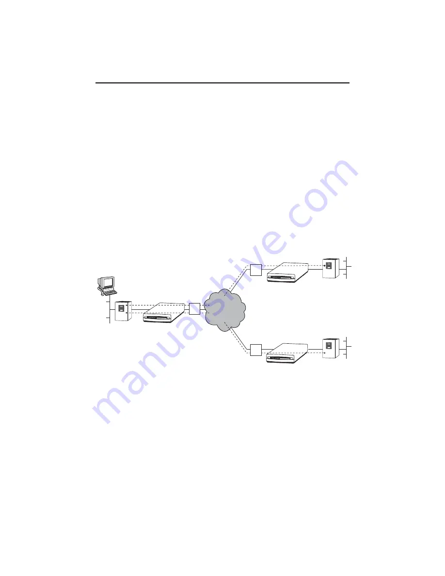
See the following illustration for an example of a network that includes iMarc units at the
central site (for example, the company’s headquarters in Munich) and the remote sites
(for example, branch offices in London and Singapore). User data PVCs provide
LAN-to-LAN connectivity between the central site and the remote sites.
From a network management perspective, the central site iMarc unit should be
configured for management from a Network Management System (NMS), through either
the attached router, as shown in the above figure, or through the Network Operations
Center (NOC) router (for management by the Network Service Provider). Multiple
management PVCs then connect the central site unit to the remote site units using
Paradyne’s proprietary PVC multiplexing method (embedded DLCIs).
Frame
Relay
Router
Central Site
iMarc
Unit
NMS
Munich
Headquarters
Port NET
NTU
NTU
NTU
NET Port
Frame
Relay
Router
Remote Site
iMarc
Unit
London Office
DLCI/EDLCIs:
100/0 User Data
100/2 Management Data
NTU
NTU
NTU
London Office
London Office
NTU
NTU
NTU
NET Port
Frame
Relay
Router
Remote Site
iMarc
Unit
Singapore Office
DLCI/EDLCIs:
200/0 User Data
200/2 Management Data
Network
100
200
DLCI/EDLCIs:
100/0 User Data for London
200/0 User Data for Singapore
100/2 Management Data for London
200/2 Management Data for Singapore
03-17376
NTU


