background image

2. Installation

8820-A2-GN20-30

March 2001

2-5

Mounting Configurations 

The Hotwire 8820 GranDSLAM chassis comes equipped with mounting brackets 
to support installation in 19-inch Electronic Industries Association (EIA)-type or 
23-inch NEBS-type racks. Installation of the 8820 chassis in a European 
Telecommunication Standards Institute (ETSI)-type rack requires a different set of 
custom mounting brackets.

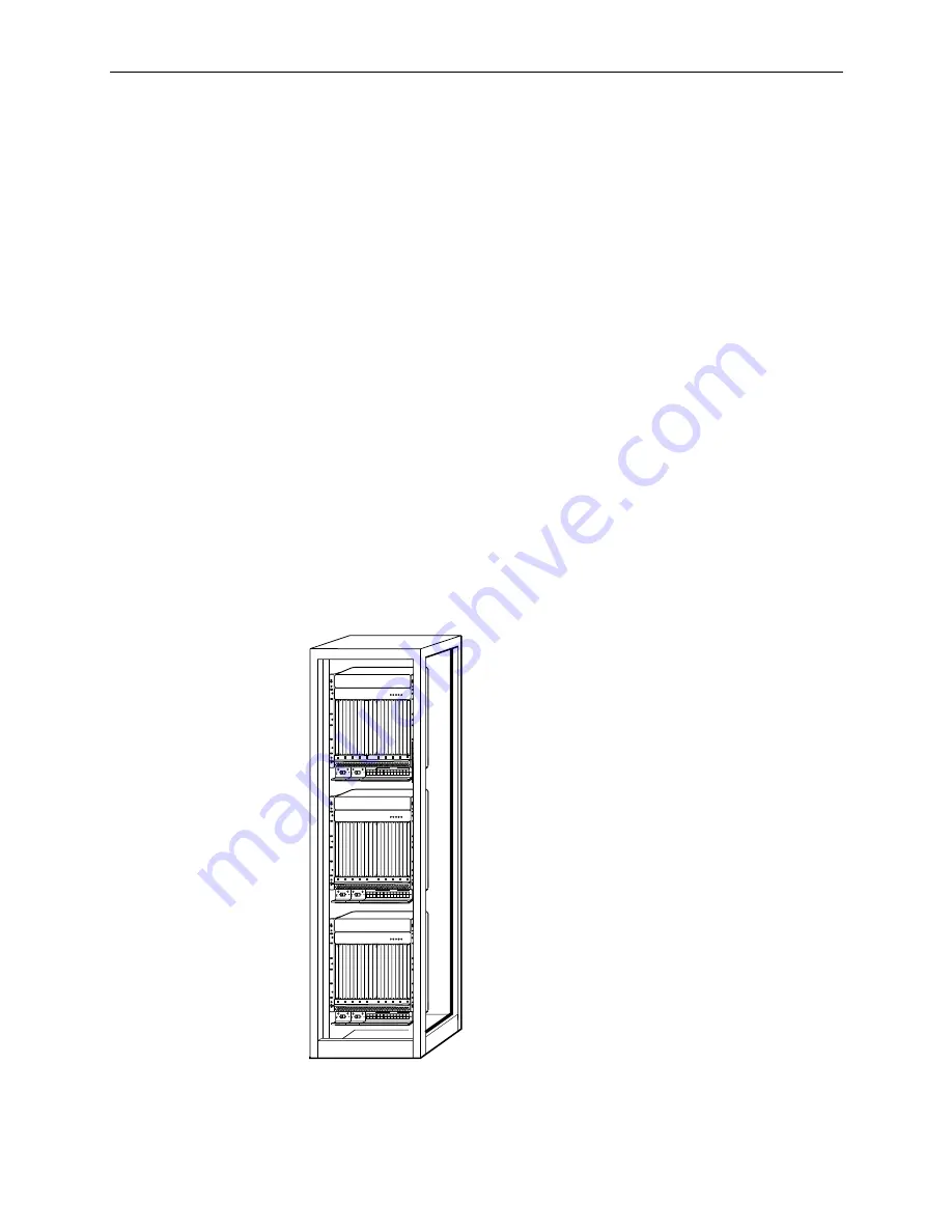
The following figure depicts an example of a chassis mounting configuration with 
three chassis in a rack.

CAUTION:

Although three GranDSLAM chassis will fit into one rack, be sure that 
after all circuit cards are installed, the final configuration does not 
exceed NEBS heat release requirements. NEBS requirements for a rack 
of this size is 181.2 watts per square foot. When using a standard 
transmission bay (12 inch-deep frame), the footprint is 7 square feet. 
This equals 1268 watts maximum per frame or rack when used in a NEBS 
location.

NOTE:

In this guide, the term 

rack 

refers to a CO rack, cabinet, frame, or bay.

ALARMS

Major Minor

Fan

B

A

POWER

SERIAL
SMCM

CLOCK

A

ALARM

2

4

6

8

10

12

14

16

18

1

3

5

7

9

11

13

15

17

LAN/WAN  SLOT

B

CLOCK

B

A

SERIAL

MCC

AC

ALARM

48V R

T

N

48V NEG

POWER ENTRY MODULE

LEFT UNIT: LINE A
RIGHT UNIT: LINE B

WARNING! POWER MUST BE DISCONNECTED AT THE SOURCE
BEFORE REMOVING OR INSTALLING THIS PWR ENTRY MODULE

48V R

T

N

48V NEG

POWER ENTRY MODULE

LEFT UNIT: LINE A
RIGHT UNIT: LINE B

WARNING! POWER MUST BE DISCONNECTED AT THE SOURCE
BEFORE REMOVING OR INSTALLING THIS PWR ENTRY MODULE

00-15281a-03

Three Hotwire Chassis

in a Rack

ALARMS

Major Minor

Fan

B

A

POWER

SERIAL
SMCM

CLOCK

A

ALARM

2

4

6

8

10

12

14

16

18

1

3

5

7

9

11

13

15

17

LAN/WAN  SLOT

B

CLOCK

B

A

SERIAL

MCC

AC

ALARM

48V R

T

N

48V NEG

POWER ENTRY MODULE

LEFT UNIT: LINE A
RIGHT UNIT: LINE B

WARNING! POWER MUST BE DISCONNECTED AT THE SOURCE
BEFORE REMOVING OR INSTALLING THIS PWR ENTRY MODULE

48V R

T

N

48V NEG

POWER ENTRY MODULE

LEFT UNIT: LINE A
RIGHT UNIT: LINE B

WARNING! POWER MUST BE DISCONNECTED AT THE SOURCE
BEFORE REMOVING OR INSTALLING THIS PWR ENTRY MODULE

Summary of Contents for Hotwire 8820 GranDSLAM Series

Page 1: ...Hotwire 8820 GranDSLAM Installation Guide Document No 8820 A2 GN20 30 March 2001 ...

Page 2: ...al sales representative service representative or distributor directly for any help needed For additional information concerning warranty sales service repair installation documentation training distributor locations or Paradyne worldwide office locations use one of the following methods Internet Visit the Paradyne World Wide Web site at www paradyne com Be sure to register your warranty at www pa...

Page 3: ...urce is to be reliably connected to earth Connect the earthing grounding wire to the protective earthing grounding lug connector identified by the protective earth symbol 8 Do NOT apply power to both front and rear terminal blocks simultaneously 9 A readily accessible disconnect device as part of the building installation shall be incorporated in fixed wiring The disconnect device a 48 VDC 35A cir...

Page 4: ...equirements as prescribed in the appropriate Terminal Equipment Technical Requirements document s The Department does not guarantee the equipment will operate to the user s satisfaction Before installing this equipment users should ensure that it is permissible to be connected to the facilities of the local telecommunications company The equipment must also be installed using an acceptable method ...

Page 5: ... limits as amended by Directive 93 68EEC Directive 89 336 EEC Council Directive of 3 May 1989 on the approximation of the laws of the member states relating to Electro Magnetic Compatibility EMC as amended by Directive 93 68 EEC Japan Class A ITE This is a Class A product based on the standard of the Voluntary Control Council for interference by Information Technology Equipment VCCI If this equipm...

Page 6: ...E March 2001 8820 A2 GN20 30 ...

Page 7: ...ositioning the Mounting Brackets for 19 Inch EIA Type or 23 Inch NEBs Type Racks 2 6 Changing the Setback Position of the Mounting Brackets 2 7 Installation into a 19 Inch or 23 Inch Rack 2 8 Installation into a Rack without Threaded Screw Holes 2 9 Installing the Air Filter 2 10 Connecting Power 2 11 Front Power Access 2 11 Rear Power Access 2 13 Insertion or Removal of the PEMs 2 15 Populating t...

Page 8: ...ctions to the IPC Ethernet Hubs or Switches 3 6 Connecting to an SNMP Management System 3 7 Connecting to a Terminal or Personal Computer PC 3 7 Connecting to a Modem for Remote Management 3 8 Hot Insertion or Removal of the SIM 3 8 4 Troubleshooting Troubleshooting Table 4 1 LEDs 4 2 A Pinouts 8 Pin Modular Alarm Connector A 1 Telco 50 pin Connector Pinouts for DSL Loops and POTS Splitters A 2 8 ...

Page 9: ...tion Provides general information about what types of cards can be used in the 8820 GranDSLAM and GranDSLAM features Chapter 2 Installation Describes what is supplied with the Hotwire 8820 GranDSLAM how to install it and how to install cards into the chassis Chapter 3 Cabling Describes how to install various cables used by the 8820 GranDSLAM and its cards Chapter 4 Troubleshooting Lists suggested ...

Page 10: ... Installation Instructions 8312 A2 GZ40 Hotwire 8312 8314 MVL and ReachDSL MVL Cards Installation Instructions 8335 A2 GB20 Hotwire ATM Line Cards Models 8335 and 8365 User s Guide 8335 A2 GZ40 Hotwire ATM Line Cards Models 8335 and 8365 Installation Instructions 8343 A2 GZ40 Hotwire 8343 8344 Packet SDSL Cards Installation Instructions 8373 A2 GZ40 Hotwire 8373 8374 RADSL Cards Installation Instr...

Page 11: ...ion across multiple DSL port cards With every slot populated each GranDSLAM shelf can support up to 408 DSL ports The GranDSLAM chassis allows addressable diagnostic connectivity between the MCP and each of the DSL cards It also converts and distributes 48V power to the cards in the chassis In addition it provides fans to cool the circuit cards in the rack The following illustration shows a high l...

Page 12: ... cards that interoperate with the Hotwire 6310 MVL and 6350 ReachDSL modems 8510 4 port and 8373 12 port Rate Adaptive Digital Subscriber Line RADSL card that interoperates with the 5620 Remote Termination Unit RTU or the 6371 RADSL Router 8303 24 port Integrated Services Digital Network ISDN Digital Subscriber Line IDSL card that interoperates with the 6301 and 6302 IDSL Routers 8343 24 port Pack...

Page 13: ...rfaces on the front panel 8784 8785 and 8786 2 port TDM SDSL cards 8774 8775 and 8776 4 port TDM SDSL cards 8777 and 8779 8 port TDM SDSL cards NOTE RADSL MVL ReachDSL MVL IDSL SDSL ATM SDSL ATM ADSL and TDM SDSL cards are generically referred to as DSL cards in this document ...

Page 14: ...by the system This happens automatically without system disruption NOTE When using either front or rear power access two separate power sources must be provided to enable the power redundancy function of the chassis Also the PEMs A and B must be installed even though rear power is used Major Minor Alarm Contacts for CO Alarm Requirements The GranDSLAM provides two sets of dry contacts via the Syst...

Page 15: ...ow at least 4 inches between the back of the rack and a solid wall Otherwise allow at least 6 inches Take care that other equipment does not blow hot air into the front and side air intakes on the GranDSLAM chassis Power The GranDSLAM operates from a standard CO 48 VDC power supply 42 0 to 57 0 VDC The power source wires must be 8 AWG solid or stranded Grounding A copper lug connector is attached ...

Page 16: ...required 8 pin shielded CAT5 modular cable is required for connection to the DSL 10 100BaseT Ethernet ports You will need this cable for each RADSL IDSL Packet SDSL ReachDSL MVL and MVL card in the GranDSLAM For ATM SDSL and TDM SDSL cards refer to the appropriate card Installation Instructions for the correct cable needed 8 pin UTP unshielded twisted pair CAT5 modular cable may be used for connec...

Page 17: ...ality These cards are not provided with this product and must be ordered separately 00 16264a 02 Multislot Filler Plates with Receptacles MCP Card Fan Module inside System Interface Module Power Entry Modules DSL Card Mounting Bracket Mounting Bracket 1 Inch Wide Single Slot Filler Plates 0 8 Inch Wide Single Slot Filler Plate SERIAL SMCM CLOCK A ALARM 2 4 6 8 10 12 14 16 18 1 3 5 7 9 11 13 15 17 ...

Page 18: ...nnectors 4 small cable bushings 5 wire ring tongue terminals for use with the power source wires 18 cable ties to attach the Tip and Ring cables to DSL cards should locking pivot brackets not be used Additional hardware in a separate plastic bag 18 locking pivot brackets and screws for use with the customer provided cables used on the rear of the chassis Be sure to register your warranty at www pa...

Page 19: ...48V RTN 48V NEG POWER ENTRY MODULE LEFT UNIT LINE A RIGHT UNIT LINE B WARNING POWER MUST BE DISCONNECTED ATTHE SOURCE BEFORE REMOVING OR INSTALLINGTHIS PWR ENTRY MODULE 48V RTN 48V NEG POWER ENTRY MODULE LEFT UNIT LINE A RIGHT UNIT LINE B WARNING POWER MUST BE DISCONNECTED ATTHE SOURCE BEFORE REMOVING OR INSTALLINGTHIS PWR ENTRY MODULE 00 15281a 03 Three Hotwire Chassis in a Rack ALARMS Major Mino...

Page 20: ...ovided with the chassis Mounting Brackets Configuration The chassis is equipped with reversible mounting brackets installed on the chassis with a 1 inch setback and configured for a 19 inch rack You may reposition them for a flush 3 inch or 5 inch setback and or reconfigure them for a 23 inch NEBS type rack Positioning the Mounting Brackets for 19 Inch EIA Type or 23 Inch NEBs Type Racks The mount...

Page 21: ...dure 1 Remove the screws three on each side that hold the mounting brackets to the chassis 2 Reposition the brackets for the desired setback flush 1 inch 3 inch or 5 inch Refer to procedures for reversing brackets if installing in a 23 inch rack in Positioning the Mounting Brackets for 19 Inch EIA Type or 23 Inch NEBs Type Racks on page 2 6 3 Replace and tighten the three screws on each side to at...

Page 22: ... screws on each side of the rack Use the screwdriver to install two screws loosely enough to allow the bracket keyholes to drop over the screw heads during installation 2 Place the chassis against the front rails of the rack allowing the installed mounting screws to pass through the keyholes Lower the chassis into place allowing the keyholes to slide under the screw heads This action positions the...

Page 23: ... the chassis Mark the appropriate locations for the machine screws on the rack 2 Slip a Speed Nut onto each rail hole selected and align the hole of the Speed Nut with the hole in the rail 3 Line up the chassis mounting bracket with the Speed Nut and start to rotate the Speed Nut screw into the chassis mounting bracket and the Speed Nut Start all screws then tighten all screws until each screw hea...

Page 24: ...lide the filter upwards until it seats against the foam strip located on the backplane NOTE When oriented properly the vertical arrows on the front and rear edges of the filter point up 3 Replace the vent cover plate ensuring that the plate s foam strip presses against the front of the filter 4 Replace the screws ALARMS Major Minor Fan B A POWER SERIAL SMCM CLOCK A ALARM 2 4 6 8 10 12 14 16 18 1 3...

Page 25: ...t be made to both at the same time Front Power Access Front power access is made via two PEMs which are located in the front lower left side of the chassis PEM A is located on the left while PEM B is on the right NOTE Both PEMs must be powered or else the MCP alarm will activate The 48 VDC power wiring requires the use of 8 AWG stranded wires Use the following procedure to connect power to the fro...

Page 26: ...talled see Step 1 to the power taps using the M4 Phillips head screws Connect the 48V wire to the power tap on the right 48V NEG is printed on the front of the PEM s faceplate Connect the 48V RTN return or wire to the power tap on the left 48V RTN is printed on the front of the faceplate Tighten the M4 screws securely to the power taps while keeping the ring tongue terminals and their wires dresse...

Page 27: ... has been disconnected at the source When installing or servicing rear access power connections never remove both metal covers at the same time to avoid exposure to 48 VDC potentials NOTE Both PWR A and PWR B must be powered or else the MCP alarm will activate 00 16647 01 M4 Phillips head Screws 10 11 12 13 14 15 16 17 18 9 8 7 6 5 4 3 2 1 CAUTION USE NO 8 AWG ONLY 48V RTN PWR A PWR B 48V RTN Powe...

Page 28: ...or the metal cover 4 Route the rear access power wires either up through the bottom of the chassis or straight through the cover plate 5 Remove the two M4 Phillips head screws installed in the power taps on the backplane 6 Dress the power wires with the ring tongue terminals attached in Step 1 through the appropriate access holes Attach the 8 AWG wires to the power taps using the M4 Phillips head ...

Page 29: ...VE DEVICES This product is designed to protect sensitive components from damage due to electrostatic discharge ESD during normal operation When performing installation procedures however take proper static control precautions to prevent damage to equipment If you are not sure of the proper static control precautions contact your nearest sales or service representative NOTE The GranDSLAM is equippe...

Page 30: ... A replacement DSL port card will be assigned a MAC address for the slot as stored in the SIM Replacing the SIM will result in a new MAC address being assigned to all slots Slot Is Shipped with Can Accept These Cards See 1 7 10 16 Two multislot filler plates left covering Slots 1 7 and right covering Slots 10 17 DSL Installing DSL Cards into Slots 1 6 and 10 17 on page 2 18 9 Single 0 8 inch fille...

Page 31: ...Ds turn ON and OFF briefly When the self test is completed successfully the SYSTEM OK LED will turn ON Make sure the OK SYSTEM indicator on the MCP faceplate is ON blinking green 5 Secure the MCP card by tightening the top and bottom screws on the faceplate This is required to ensure proper pressure on the EMI gaskets and to maintain proper air flow ALARMS Major Minor Fan B A POWER SERIAL SMCM CLO...

Page 32: ...17 Two multislot filler plates for Slots 1 through 7 and 10 through 16 If you are installing DSL cards in Slots 1 through 8 or 11 through 17 you will need to remove a multislot filler plate After installing the card you will need to adjust the remaining portion of the filler plate according to the number of cards being installed and then reinstall the filler plate The following table of procedures...

Page 33: ...nels from the side of the filler plate opposite the EMI gaskets The edge with the the EMI gaskets is needed to create a good EMI seal with the card in the slot to the left of the filler plate ALARMS Major Minor Fan B A POWER SERIAL SMCM CLOCK A ALARM 2 4 6 8 10 12 14 16 18 1 3 5 7 9 11 13 15 17 LAN WAN SLOT B CLOCK B A SERIAL MCC AC ALARM 48V RTN 48V NEG POWER ENTRY MODULE LEFT UNIT LINE A RIGHT U...

Page 34: ...gaskets on the left side of the multislot filler plate by applying slight pressure to the left 7 Replace the screws in the multislot filler plate to fasten it to the chassis ALARMS Major Minor Fan B A POWER SERIAL SMCM CLOCK A ALARM 2 4 6 8 10 12 14 16 18 1 3 5 7 9 11 13 15 17 LAN WAN SLOT B CLOCK B A SERIAL MCC AC ALARM 48V RTN 48V NEG POWER ENTRY MODULE LEFT UNIT LINE A RIGHT UNIT LINE B WARNING...

Page 35: ...is necessary for EMI shielding and proper cooling Installing DSL Cards into Slots 8 and 18 If you are installing only one DSL card in your GranDSLAM it is recommended that you install it in Slot 1 However if you have used all your other DSL slots 1 7 and 10 17 you can then install the last cards in Slots 8 and 18 Do not install DSL cards into Slots 9 A or B If you are installing more than one DSL ...

Page 36: ...indicator on the DSL card faceplate is blinking green For a more detailed explanation of LEDs on the DSL card refer to the appropriate DSL card documentation 5 Secure the DSL card by tightening the top and bottom screws on the faceplate while applying slight pressure to the left to insure a good seal This is required to maintain proper gasket pressure on the faceplate NOTE If a new DSL card is not...

Page 37: ...e Then press in on the latches until the card is fully seated 4 Verify that the OK SYSTEM indicator on the card s faceplate is blinking green 5 Secure the card by fastening the screws on each end of the faceplate This is required to maintain proper gasket pressure on the faceplate as well as proper air flow 6 Attach the appropriate cables to the connectors protruding through the SCM faceplate ALAR...

Page 38: ...er sources both Power LEDs must be ON If you are using a single power source the appropriate Power LED either Power A or Power B must be ON The FAN ALARM LED must be OFF Also check the SYSTEM LEDs on the MCP SCM and DSL cards if you have not done so already The OK SYSTEM indicators on the cards must be winking green If these status indicators fail to appear as described see Troubleshooting Table a...

Page 39: ... Using Cable Ties or Installing Locking Pivot Brackets on page 3 2 EMI NOTICE In order to maintain compliance with Part 15 FCC Rules and other EMI requirements certain TDM SDSL port cards require the installation of the supplied ferrite choke on the 50 pin telephone network cable where it connects to the GranDSLAM The choke Part No 175 0018 0031 and its installation instructions are provided with ...

Page 40: ...he Phillips pan head screw that you replaced in Step 1 on the right side of the connector 5 Make sure the other end of the cable is connected to the appropriate POTS splitter shelf MDF or demarcation point Installing Locking Pivot Brackets The network Tip and Ring cables must be equipped with end fed plug connectors Each connector has a captive screw at one end and a tapped hole in the plastic at ...

Page 41: ...two connectors 4 Rotate the connector until it is fully seated 5 Tighten the captive screw on the top of the cable s connector to secure it to the insert mounted on the rear cover 6 Repeat this procedure for the remaining connectors Locking Pivot Bracket Receptacle on Backplane Rear Panel Cutout 99 16163d 01 Rotate 99 16163e 01 99 16163f 01 Tighten Screw ...

Page 42: ...ews three on each from the cable management brackets and then remove the cable management brackets from the chassis Reposition the brackets so that the open slots face the rear 2 Reinstall the screws in the same holes to secure the brackets to the chassis When you have correctly installed the cable management brackets ten slotted holes are exposed at each side to accept the cables and the bushings...

Page 43: ...Taking one of the split cable bushings open the bushing and slip it over the cable on the outside of the cable management bracket 3 Slide and snap the bushing into the slotted hole of the cable management bracket 4 Repeat this procedure for each of the remaining cables When you have correctly installed the split cable bushing it points toward the center of the chassis with the large diameter ring ...

Page 44: ...r connecting RADSL MVL ReachDSL MVL IDSL and SDSL cards to the IPC Ethernet hubs or switches For other types of cards refer to the appropriate Installation Instructions Procedure To connect the Hotwire 8820 GranDSLAM to the IPC Ethernet hubs or switches 1 Plug an 8 pin modular UTP CAT5 cable into LAN jack Port 1 for connecting the LAN wiring from the DSL card in Slot 1 Repeat this step for jack Po...

Page 45: ...erminal or PC 1 Connect the serial cable with 8 pin modular plugs on each end provided with the MCP card into the SERIAL MCP port of the chassis 2 Dress the cable to the right and through the cable retainer 3 Plug the other end of the cable into the terminal or PC serial port using the appropriate DB25 or DB9 adapter that is supplied with the MCP card 4 Configure your terminal or terminal emulator...

Page 46: ...SERIAL MCP port of the chassis 2 Dress the cable to the right and through the cable retainer 3 Plug the other end of the cable into your modem s serial port using a DB25 adapter and a Null Modem Hot Insertion or Removal of the SIM If the port card Ethernet interfaces are not being used it is possible to remove the SIM without disrupting user data However if the user terminal console or 10BaseT man...

Page 47: ...and DSL card is inoperative in Slot n 1 Using the Hotwire DSL software choose Card Selection from the Main Menu to display the status of each DSL card 2 If a major alarm is indicated check the Ethernet connections on the MCP card and DSL port card Make sure they are plugged in Use Hotwire DSL software to reset the DSL card A A E FAN Alarm is ON CAUTION This is a serious alarm and requires immediat...

Page 48: ...System Alarm Yellow Off Fan failure or a single fan in the Fan Module is working at less than 50 of its normal output Normal operation or no power Major Alarm Yellow Off Major alarm present on any of the cards in the chassis The card with alarm conditions will also have its Alarm LED lit No major alarms Minor Alarm Yellow Off Minor alarm present on any of the cards or Power Alarm problem in the ch...

Page 49: ...or and minor alarms to a CO alarm system The following table lists the pin assignments for the 8 pin jack Pin Number Use 1 Not Connected 2 Closed on Major Alarm Normally Open 3 Common on Major Alarm 4 Open on Major Alarm Normally Closed 5 Closed on Minor Alarm Normally Open 6 Common on Minor Alarm 7 Open on Minor Alarm Normally Closed 8 Not Connected 99 15322 02 Pin 1 Pin 8 ALM ...

Page 50: ...ts the port assignments of the slots and their respective connectors for 25 ports DSL port cards with less than 25 ports have their ports assigned in ascending order starting with port 1 For example a 12 port DSL card uses Ports 1 through 12 while Ports 13 through 25 will not be connected by the port card Pinouts for DSL Ports for Each Slot Port Pins Port Pins Port Pins Port Pins Port Pins 1 1 26 ...

Page 51: ...to a diagnostic IP network 8 Pin Modular Serial MCP Connector The 8 pin SERIAL MCP connector for asynchronous terminal interface DCE type has the following pin assignments Pin Number Use 1 TX Data 2 TX Data 3 RX Data 4 Reserved 5 Reserved 6 RX Data 7 Reserved 8 Reserved 99 15320 01 Pin 1 Pin 8 Pin 1 Pin 8 Pin Number Use 1 Reserved 2 Reserved 3 Reserved 4 Signal Ground 5 Receive Data 6 Transmit Dat...

Page 52: ...convert the 8 pin modular serial interface to a standard DB9 interface which can then be connected to a laptop computer The following table lists the pin assignments 8 Pin Modular Serial Interface Pin Number Use DB25 Interface Pin Number 1 2 Pins 1 and 2 are shorted together 3 Data Terminal Ready 20 4 Signal Ground 7 5 Receive Data 3 6 Transmit Data 2 7 Clear to Send 5 8 Request to Send 4 99 15388...

Page 53: ...watts per square foot limit The square footage allocated to a rack equipped with the 8820 GranDSLAM chassis is approximately 7 square feet This equates to a maximum permissible NEBs power dissipation of 1268 4 watts per rack An 8510 4 port RADSL card dissipates 18 watts This allows up to three 8820 GranDSLAM chassis to be installed in a single rack with two chassis being fully equipped and the thi...

Page 54: ...s for 10 100BaseT LAN connection One Management 10 100BaseT and one Management Serial interface for the MCP card Local CO alarm system major and minor alarms two pairs of dry contact closures via an 8 pin modular jack supports up to 57 VDC 0 1 amp Two rear mounted interfaces Eighteen 50 pin Telco type connectors for DSL loop interfaces and PWR A and PWR B DC power access One rear mounted ground lu...

Page 55: ...elps the network administrator manage devices using Simple Network Management Protocol SNMP and HP OpenView DHCP Dynamic Host Configuration Protocol A Microsoft protocol for dynamically allocating IP addresses DHCP server A server which uses DHCP to allocate network addresses and deliver configuration parameters to dynamically configured hosts DS3 Digital Signal level 3 A digital signal transmitte...

Page 56: ...Media specific Access Control A protocol where packets transmitted over LAN ports are encapsulated in Ethernet II MAC frames MAC Address Media Access Control Address The unique fixed address of a piece of hardware normally set at the time of manufacture and used in LAN protocols MCC card Management Communications Controller Card The card in a Hotwire DSLAM system or stack that is used primarily fo...

Page 57: ...isting twisted pair line that permits high bandwidth bidirectional transmission SIM System Interface Module A module that provides user interface connections on the front of the Hotwire 8820 GranDSLAM chassis SN Service Node The endpoint modem at the customer premises also known as a Remote Termination Unit RTU SNMP Simple Network Management Protocol Protocol for open networking management TCP Tra...

Page 58: ...Glossary GL 4 March 2001 8820 A2 GN20 30 ...

Page 59: ...ch rack 2 8 in rack without threaded screwholes 2 9 CO alarm contacts 1 4 configuration 1 1 connection alarm 3 6 Ethernet 3 6 modem 3 8 PC 3 7 SNMP 3 7 terminal 3 7 cooling and air handling B 1 D document purpose iii DSL 2 18 DSL ports 1 1 E Ethernet connections 3 6 F filler plates 2 16 2 18 G grounding 2 1 B 1 H Hotwire 8820 GranDSLAM description 1 1 features 1 4 mounting configurations 2 5 I IDS...

Page 60: ...r DSL loops and POTS splitters A 2 8 pin modular alarm connector A 1 8 pin modular LAN and 10BaseT connector A 3 8 pin modular serial MCP connector A 3 DB25 adapter A 4 DB9 adapter A 4 power 2 1 2 11 B 1 power redundancy 1 4 preinstallation 2 1 product related documents iv R rack installation 2 8 RADSL 1 2 rear power access 2 13 related documents iv S SCM 1 2 2 23 SCM card 2 15 SIM 3 8 site 2 1 SN...

Reviews: