


A. Connectors and Pin Assignments
2600-A2-GN20-40
March 2005
A-5
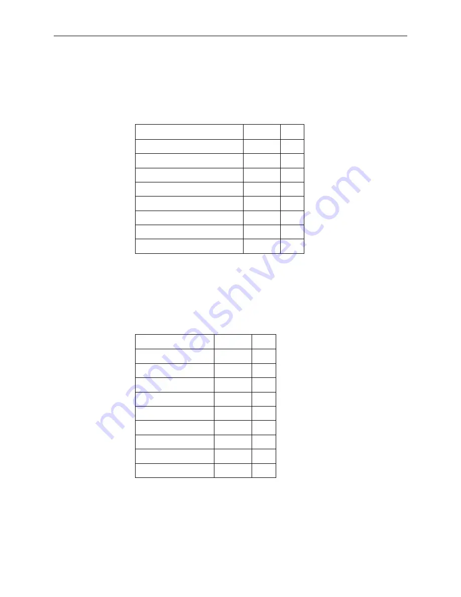
E1 and T1 Uplink Connectors
The E1 and T1 connectors on T1/E1 MLPPP models are single, RJ48C, unkeyed,
shielded, 8-pin modular jacks. The shield is connected to ground via the module.
Console Port Connector
The CONSOLE port connector is a DB9 socket connector that supports an
EIA-232-E circuit as shown in
Table A-6
.
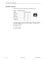
Table A-5. E1 Uplink Connectors
Signal
Direction Pin
Receive Ring
In
1
Receive Tip
In
2
NC
—
3
Transmit Ring
Out
4
Transmit Tip
Out
5
NC
In
6
NC
—
7
NC
—
8
Table A-6. Console Port Connector
RS-232 Signal
Direction Pin
Data Carrier Detect
Out
1
Receive Data
Out
2
Send Data
In
3
Data Terminal Ready
In
4
Ground
—
5
Data Set Ready
Out
6
Request to Send
In
7
Clear to Send
In
8
Ring Indicator
—
9


