background image

3. Using the Web Interface

6388-A2-GB20-00

February 2005

3-9

Tools (at the top of the page) and select System Commands. At the System 
Commands page, click on Save All.

PPPoA Connection Setup

PPPoA is defined in the Internet standard RFC 2364. It is a method of 
encapsulating PPP packets over ATM cells which are carried over the DSL line. 
PPP (Point-to-Point Protocol) is a method of establishing a network session 
between network hosts. It usually provides a mechanism of authenticating users. 
LLC and VC are two different methods of encapsulating the PPP packet. Contact 
your ISP to make sure which encapsulation is being supported. 

By selecting PPPoA, you are forcing your router to act as the termination point for 
the PPPoA connection. This frees up your PC resources and allows multiple users 
to utilize the PPPoA connection.

To configure the router for PPPoA:

Procedure

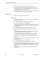
1. Click on Setup and then click on New Connection. The default PPPoE 

connection setup is displayed. 

2. At the Type field, select PPPoA from the drop-down list. The PPPoA 

connection setup page is displayed. 

3. Give your PPPoA connection a unique name. The name must not have spaces 

and cannot begin with numbers. 

4. Select or enter a VPI and VCI (as supplied by your DSL service provider or 

your ISP), or click in Auto PVC. (Auto PVC causes the router to perform  
automatic VPI/VCI detection as defined in DSL forum TR-068.) 

5. Select NAT and Firewall if you want them active for this connection. Firewall 

and NAT services must be enabled. See 

Firewall/NAT Services

 on page 3-22.

6. Select the encapsulation type (LLC or VC); if you are not sure just use the 

default mode. 

7. Select the quality of service (QOS). Leave the default value if your ISP did not 

provide this information. Depending on the QoS you select, you may also 
enter:

— PCR (Peak Cell Rate)

— SCR (Sustainable Cell Rate)

— MBS (Maximum Burst Size)

— CDVT (Cell Delay Variation Tolerance)

Following is a description of the different options:

„

Username – The username for the PPPoA access. This is provided by your 
DSL service provider or your ISP.

Summary of Contents for 6388

Page 1: ...6388 Wireless Router User s Guide Document No 6388 A2 GB20 00 February 2005...

Page 2: ...ocumentation training distributor locations or Paradyne worldwide office locations use one of the following methods Internet Visit the Paradyne World Wide Web site at www paradyne com Be sure to regis...

Page 3: ...this product must be provided by one of the following 1 a UL Listed CSA certified power source with a Class 2 or Limited Power Source LPS output for use in North America or 2 a certified transformer...

Page 4: ...with this product It has been designed to be connected to a compatible modular jack that is also compliant The Ringer Equivalence Number or REN is used to determine the number of devices that may be...

Page 5: ...formity indicating that Industry Canada technical specifications were met It does not imply that Industry Canada approved the equipment NOTICE The Ringer Equivalence Number REN for this terminal equip...

Page 6: ...E February 2005 6388 A2 GB20 00...

Page 7: ...nt Panel 1 2 Packing List 1 3 2 Hardware Installation and PC Setup Overview 2 1 Connecting the Hardware 2 1 Configuring Your PC s IP Address 2 3 Assigning an IP Address to your PC Automatically by DHC...

Page 8: ...8 Configuring the LAN 3 19 Enable Disable DHCP 3 19 Changing the Router s IP address 3 20 Ethernet Switch 3 21 Firewall NAT Services 3 22 Advanced 3 23 UPnP 3 23 SNTP 3 24 SNMP 3 25 IP QoS 3 26 Port F...

Page 9: ...er 3 49 Ping Test 3 50 Modem Test 3 51 Status 3 52 4 Troubleshooting The Router Is Not Functional 4 1 You Cannot Connect to the Router 4 1 LEDs Blink in a Sequential Pattern 4 2 Status LED Continues t...

Page 10: ...Contents iv February 2005 6388 A2 GB20 00...

Page 11: ...ww paradyne com Select Support Technical Manuals To order a paper copy of a Paradyne document or to speak with a sales representative please call 1 727 530 2000 Section Description Chapter 1 Introduct...

Page 12: ...About This Guide vi February 2005 6388 A2 GB20 00...

Page 13: ...nes too long or too noisy for ADSL ADSL R is technology that combines ADSL and ReachDSL in one device The Model 6388 is a Digital Subscriber Line DSL modem that may be set by you to run in bridge or r...

Page 14: ...to your phone line PHONE port This allows a phone to directly connect to the router You do not need to add splitter to the phone you connect here since the router has an internal splitter RESET Button...

Page 15: ...lickering a PPP connection is established and there is activity on the link LAN 1 4 LED Each LAN LED serves two purposes If the LED is continuously lit the Ethernet interface is successfully connected...

Page 16: ...1 Introduction 1 4 February 2005 6388 A2 GB20 00...

Page 17: ...d connect the other end of the cable to your phone jack 2 If you would like to use a phone in the vicinity of the router connect it to the PHONE jack of the router using the cord that came with your t...

Page 18: ...or power strip The supplied power adapter may look different than the one illustrated here Figure 2 1 Hardware Installation 5 Configure your router and your wireless devices to communicate with each...

Page 19: ...an IP address automatically instead of Use the following IP address in the following procedures By default the LAN port IP address of the router is 192 168 1 1 You can change this address or another...

Page 20: ...ry 2005 6388 A2 GB20 00 4 Ensure that the check box to the left of the item labeled Internet Protocol TCP IP is checked and click on Properties Figure 2 2 Network Connections in Windows XP Figure 2 3...

Page 21: ...close the Control Panel Windows 2000 To configure the IP address under Windows 2000 Procedure 1 In the Windows task bar click on the Start button point to Settings and then select Control Panel 2 Doub...

Page 22: ...lick in the radio button labeled Use the following IP address and type 192 168 1 x where x is any number between 2 and 254 in the IP Address field Type 255 255 255 0 in the Subnet Mask field 12 Click...

Page 23: ...e Windows task bar click on the Start button point to Settings and then click on Control Panel 2 Double click on the Network icon The Network dialog box is displayed with a list of currently installed...

Page 24: ...led in which case you can skip to Step 9 4 If TCP IP does not appear as an installed component click on Add 5 In the Select Network Protocol dialog box select TCP IP and then click on OK You may be pr...

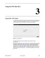
Page 25: ...er name is Admin and the password is Admin Both are case sensitive Note Before configuring your router make sure you have followed the instructions in Chapter 2 Hardware Installation and PC Setup You...

Page 26: ...er status connection information and other useful information The center display is where most of the configuration will take place Click on Log Out to close the session Refresh to update the status d...

Page 27: ...3 Using the Web Interface 6388 A2 GB20 00 February 2005 3 3 Figure 3 3 Quick Start DHCP Figure 3 4 Quick Start PPPoE...

Page 28: ...nology for a description of a firewall Username PPPoE Enter the user name given to you by your service provider Password PPPoE Enter the password given to you by your service provider IP Address Stati...

Page 29: ...n your Internet Service Provider ISP Most of the configuration you will perform will be in this area Local Area Network Connection On the other side of your router are your own Local Area Network LAN...

Page 30: ...ultiplexing mode Your DSL training mode default is MMODE If you use PPPoA or PPPoE you also need these values from your ISP Your username and password If you use multiprotocol encapsulation over ATM A...

Page 31: ...d 3 Give your PPPoE connection a unique name The name must not have spaces and cannot begin with numbers 4 Select a PVC Sharing type of Disable Enable or VLAN 5 Select or enter a VPI and VCI as suppli...

Page 32: ...e Maximum Transmission Unit the DSL connection can send It is a negotiated value The maximum specified value is 1500 although some DSL ISP providers require a larger value The minimum MTU value is 128...

Page 33: ...The default PPPoE connection setup is displayed 2 At the Type field select PPPoA from the drop down list The PPPoA connection setup page is displayed 3 Give your PPPoA connection a unique name The na...

Page 34: ...the On Demand option is not enabled this value specifies the length of time to keep the connection from being shut down for inactivity by sending PPP LCP echoes to the PPP server To ensure that the l...

Page 35: ...must not have spaces and cannot begin with numbers 4 Optionally enable Network Address Translation NAT and the Firewall options Firewall and NAT services must be enabled See Firewall NAT Services on p...

Page 36: ...o assignment To configure the router for a DHCP connection Procedure 1 Click on Setup and then click on New Connection The default PPPoE connection setup is displayed 2 At the Type field select DHCP T...

Page 37: ...DVT Cell Delay Variation Tolerance If your DSL line is connected and your DSL provider is supporting DHCP you can click on the Renew button and the CPE will retrieve an IP Address Subnet Mask and Defa...

Page 38: ...see Figure 3 11 3 Give your Bridge connection a unique name the name must not have spaces and cannot begin with numbers 4 Select a PVC Sharing type of Disable Enable or VLAN 5 Select or enter a VPI a...

Page 39: ...lt PPPoE connection setup is displayed 2 At the Type field select CLIP and the CLIP connection setup page is displayed 3 Give your CLIP connection a unique name the name must not have spaces and canno...

Page 40: ...s at the top of the page and select System Commands At the System Commands page click on Save All Modify an Existing Connection To modify an existing connection Procedure 1 From the Home screen click...

Page 41: ...odem This will bring up the Modem Setup screen Leave the default value if your ISP did not provide this information For most cases this screen should not be modified Figure 3 13 Modem Setup The Apply...

Page 42: ...tion VPI 0 VCI 34 examines incoming packets looking for ICMP Echo Requests If the TSML connection receives five ICMP Echo Request packets with the same destination IP address within five seconds it ad...

Page 43: ...nning on your network do not enable a second DHCP server To enable DHCP Procedure 1 From the Home screen click on Setup 2 Under LAN Setup select LAN Configuration The LAN Group 1 Configuration screen...

Page 44: ...DHCP relay it is responsible for forwarding the requests and responses negotiating between the DHCP clients and the server If the DHCP server and relay are turned off you must configure the IP addres...

Page 45: ...ve All Ethernet Switch To set the speed and duplex mode of the LAN ports Procedure 1 From the Home screen click on Ethernet Switch The Ethernet Switch screen appears 2 For Physical Port1 through Physi...

Page 46: ...unselecting the Enable Firewall and NAT Services button the firewall and NAT services is disabled for all WAN connections Enabling Firewall NAT does not automatically apply it to connections The Apply...

Page 47: ...active DSL connection In the presence of multiple DSL connections select the one over which the incoming traffic will be present such as the default Internet connection To enable UPnP you must first...

Page 48: ...To use SNTP Procedure 1 From the Home screen click on Advanced and under Advanced select SNTP The SNTP screen appears 2 Enable SNTP and then specify one or more SNTP servers 3 The Apply button will te...

Page 49: ...lic sysObjectID for the router IP address of the agent sending the trap Time stamp sysUpTime Serial Number of the router IP address of the router Interface name To configure SNMP Procedure 1 From the...

Page 50: ...Using the Port Forwarding page you can provide local services such as web hosting for people on the Internet When users send this type of request to your network via the Internet the router will forw...

Page 51: ...screen click on Advanced and under Advanced select Port Forwarding First select the IP address for your Netmeeting server Next select the Audio Video category and add Netmeeting to the Applied Rules b...

Page 52: ...he LAN Group from the drop down list that these changes will apply to 3 Select a LAN IP address from the LAN IP drop down list Click on New IP to add a new IP address to the list 4 Select available ru...

Page 53: ...P address Once the IP address has been added to you can apply Port Forwarding rules to this IP address 3 The Apply button will temporarily save these settings To make the change permanent click on Too...

Page 54: ...ome screen click on Advanced 2 Under Advanced select Bridge Filters The Bridge Filters screen appears as shown in Figure 3 26 Bridge Filters The User Interface for Bridge Filter allows the user to add...

Page 55: ...ese rules are entered automatically by the system to ensure that you don t lock yourself out of the system The first rule allows all ARP frames through the system The second rule allows all IPv4 frame...

Page 56: ...led if NAT is also enabled To enable Multicasting Procedure 1 From the Home screen click on Advanced 2 Under Advanced select Web Filters 3 Select features to be enabled and disabled over the router 4...

Page 57: ...t groups It should only be enabled if NAT is also enabled To enable Multicasting Procedure 1 From the Home screen click on Advanced 2 Under Advanced select Muliticast 3 The Apply button will temporari...

Page 58: ...Apply button will temporarily save these settings To make the change permanent click on Tools and select System Commands On the System Commands page click on Save All Figure 3 29 IGMP Snooping Static...

Page 59: ...een the router and the remote network or host 5 Specify the Metric This determines the maximum number of steps between network nodes that data packets will travel A node is any device on the network s...

Page 60: ...v2 format using multicasting 4 Specify the Direction This determines the direction that RIP routes will be updated Selecting In means that the router will only incorporate received RIP information Sel...

Page 61: ...tion To enable any of the Access Control features Procedure 1 From the Home screen click on Advanced 2 Under Advanced select Access Control The Access Control screen appears All Access Control rules h...

Page 62: ...Setup screen appears 3 Enter or select the parameters described in Table 3 2 Wireless Setup Figure 3 33 Wireless Setup Screen Table 3 2 Wireless Setup 1 of 2 Parameter Description Enable AP Enabling t...

Page 63: ...1 11 for the router to use Recommended values are 1 6 and 11 These three values do not overlap and could be used by three neighboring wireless LANs 802 11 Mode Specify whether the router will support...

Page 64: ...ireless Configuration screen appears Figure 3 34 Wireless Configuration Screen The Apply button will temporarily save these settings To make the change permanent click on Tools at the top of the page...

Page 65: ...on key as defined on this screen If an Authentication Type of Shared is selected the client must properly encrypt a packet sent by the router using the encryption key however this method allows hacker...

Page 66: ...1x Screen WPA Wi Fi Protected Access For WPA you can specify a RADIUS server as with 802 1x above or a Pre Shared Key PSK Figure 3 38 Wireless Security WPA Screen The Apply button will temporarily sav...

Page 67: ...SSIDs To use Wireless Management Procedure 1 From the Home screen click on the Wireless tab 2 From the Wireless menu click on Management The Wireless Management screen appears 3 Select Access List To...

Page 68: ...s To cause the router to advertise the wireless LAN using more than one Service Set IDentifier SSID Figure 3 41 Wireless Management Multiple SSID Screen The Apply button will temporarily save these se...

Page 69: ...y to the unit will be lost You can reconnect after the unit reboots Restore Defaults Use this button to restore the default settings selected by your service provider Connectivity to the unit will be...

Page 70: ...Severity Levels Severity Level Description Panic System panic or other condition that causes the router to stop functioning Alert Conditions that require immediate correction such as a corrupted syste...

Page 71: ...this screen The idle timeout determines after how many minutes of inactivity the web interface is logged off The Apply button will temporarily save these settings To make the change permanent click o...

Page 72: ...ate Gateway 2 Click on Browse and find the firmware file to download Make sure this is the correct file 3 Click on upgrade firmware Once the upgrade is complete the CPE will reboot You will need to lo...

Page 73: ...3 Using the Web Interface 6388 A2 GB20 00 February 2005 3 49 Figure 3 45 Update Gateway Analyzer The Analyzer screen shows link statuses and test results Figure 3 46 Analyzer...

Page 74: ...e able to access the Internet To run a ping test Procedure 1 From the Home screen under the Tools title click on Ping Test 2 Specify the target IP Address that you want to ping Optionally specify TOS...

Page 75: ...end and segment tests The test may take a few seconds to complete To perform the test select your connection from the list select a Test Type and click on the Test button Before running this test make...

Page 76: ...twork Statistics Select to view the Statistics of the Ethernet and DSL interfaces as shown in Figure 3 49 Figure 3 49 Network Statistics Connection Status Select to view the Status of different connec...

Page 77: ...ation Select to view the router s driver and run time information as shown in Figure 3 51 Figure 3 51 Product Information System Log Select to view all logged information Depending upon the severity l...

Page 78: ...3 Using the Web Interface 3 54 February 2005 6388 A2 GB20 00...

Page 79: ...ame subnet as the router you should be able to ping the router 7 Can you ping the WAN Your ISP should have provided the IP address of their server If you can ping the router and your protocols are con...

Page 80: ...to Blink This means that the DSL line is trying to train but for some reason it cannot establish a valid connection The main cause of this is that you are too far away from the central office Contact...

Page 81: ...t with However you may have several machines on your local network that want to access the Internet at the same time The router provides NAT functionality that converts your local network addresses to...

Page 82: ...tation solves the problem of supporting a large number of stations but introduces the problem of getting traffic from one subnet to another To accomplish this devices called routers are placed between...

Page 83: ...ection Setup 3 12 Enable Disable 3 19 DMZ Explained A 1 DoC D Document Feedback A Purpose and Intended Audience v Summary v duplex mode 3 21 Dynamic Routing 3 35 E EMI Notice Canada D Japan D Enable D...

Page 84: ...51 Overview 2 1 P packet size 3 50 Packing List 1 3 Password 3 1 PC Setup 2 1 Ping Test 3 50 Port Forwarding 3 26 port speed 3 21 Ports and Buttons Back Panel 1 2 Power LED 1 2 power supply 2 1 PPPoA...

Page 85: ...ing 4 1 Troubleshooting Management Link 3 18 TSML 3 18 U Update Gateway 3 48 Upgrade Firmware 3 48 UPnP 3 23 User Management 3 47 Username 3 1 V VLAN 3 29 W WAN Configuring 3 6 Connection 3 5 Warranty...

Page 86: ...Index IN 4 February 2005 6388 A2 GB20 00...

Reviews: