


2
Introduction
The PRT3 Printer Module can be used as an interface between C-Bus and your Digiplex system. When in home automation mode, the
Printer Module can receive and send commands to and from the C-Bus PC interface and the Digiplex control panel, linking your building
automation capabilities with your security system.
The Printer Module features 30 virtual PGMs for use with its building automation interface capabilities. These PGMs are not related to any
physical output on the module, but operate in the same manner and are programmed in the same way as traditional PGMs. A virtual PGM
can be used to trigger a response within C-Bus based on an event that has occurred within the Digiplex system. For example, when a user
uses the Digiplex system to disarm an area, this event could activate a virtual PGM on the Printer Module and trigger a response within C-
Bus, such as turning on a specific light on the premises. See “Virtual PGM Programming” on page 4.
Up to 30 C-Bus entries can be associated with the Printer Module’s virtual PGMs. C-Bus entries allow you to set the commands that will be
sent on the C-Bus in relation to events that occur within the Digiplex system. When the state of a virtual PGM on the Printer Module
changes, a message is sent by the C-Bus entry that is associated with that virtual PGM. See “C-Bus Entry Options” on page 8.
The Printer Module also features 16 onboard virtual inputs. These inputs are not related to any physical input on the module, but operate in
the same manner and are programmed in the same way as a traditional zone input. A virtual input can be programmed to trigger a response
from the Digiplex control panel based on an event that has occurred within C-Bus. Using virtual inputs to trigger events within the Digiplex
control panel involves associating the Printer Module’s virtual input to a zone or a keyswitch on the control panel. See “Virtual Input Options”
on page 14.
In order for C-Bus and the Digiplex control panel to communicate in such a way, the Printer Module’s serial port must be set to
communicate using the Clipsal C-Bus Protocol.
For a complete list of the Printer Module’s event reporting features, see the Printer Module V1.0 (PRT3) Instructions.
The PRT3 Printer Module is compatible with C-Bus interface firmware V4.00.00 and higher. C-Bus lighting units must be configured
with firmware V1.1 and higher.
If the Printer Module fails to connect to the C-Bus PC interface, a trouble will be generated.
Installation
The Printer Module is connected to the control panel’s combus. Connect the four terminals labeled red, black, green, and yellow of the
module to the corresponding terminals on the control panel as shown in Figure 2 on page 20. See the
EVO or DGP-848
Reference &
Installation Manual
for the maximum
allowable installation distance from the control panel.
The C-Bus PC Interface must be connected to the Printer Module’s serial port using a null modem cable only.
Overview
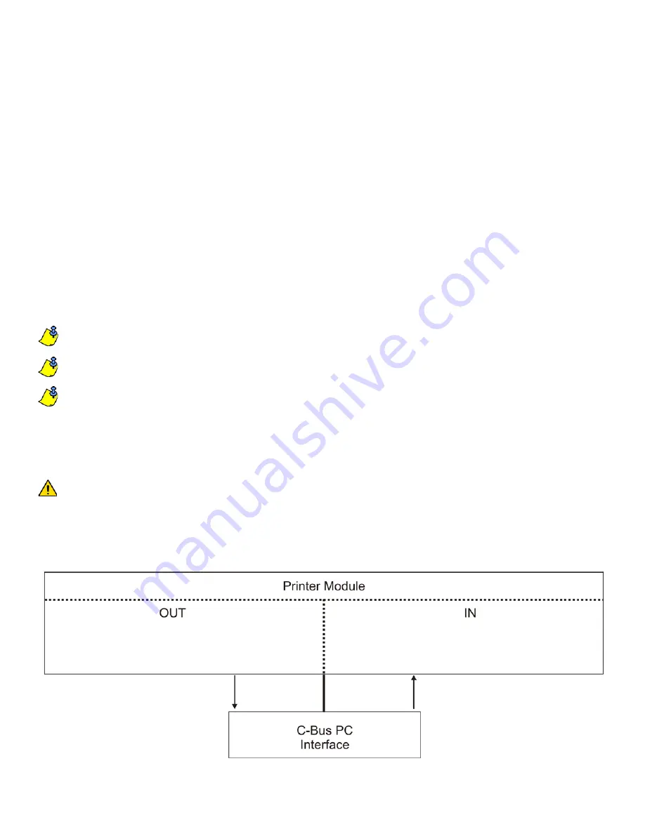
The following provides of an overview of how the Printer Module communicates with C-Bus.
Figure 1: C-Bus Overview
• Messages from C-Bus PC interface can be used to open/
close virtual inputs on the Printer Module.
• C-Bus entries are associated with Printer Module’s virtual
PGMs.
• Printer Module sends messages to C-Bus PC interface based
on virtual PGM events and C-Bus Entry programming.


