background image


/ /  .

"& %

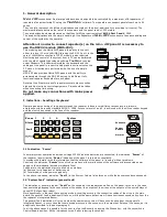
&&$3"%&

 .

"& %

&&$

1


1

1

,

1

# )

<)

"

!

 .

"& %

&&$

1

!

!

&

1

0

1


Zones By 

Pass”

;

<


0

!


()$

5*


/#

0

"# )

"

&

"

+&


Schematic 3


Schematic 4

- "6" "#

=

&+" "# ) "&" &!

:

&

0

1


<- "6" "#

&")

"

!

/!

4 0? '

3

0?

"

5*

0?

; <

& )

)

" + ""#


When we connect a PC via the RS232 module to the panel, for the 

!

1

0?

c)

!"#&(66)

%&")

"


&- /

!

0

3

!

!

&- /

0

D

D

;

<

##

0

D

*

7

E

;

<

8

th

 switch


ON


ID 1


7

th

 switch  


ON


ID 2


6

th

 switch


ON


ID 3


5

th

 switch


ON


ID 4


8

th

 & 5

th 

switches


ON


ID 5


7

th

 & 5

th

 switches 


ON


ID 6


6

th

 & 5

th

 switches


ON


ID 7


8

th

&7

th

&5

th

 switches


ON


ID 8


"&" &!

:

!"#&(66)

%

&")

"

"6" "#

&")

"


> "# )6 !"#

&(66)

%

"

"# )

"

&

Summary of Contents for Matrix 2000

Page 1: ...Repeater Repeater for Conventional Fire alarm Panels Version 1 0 October 2004 Installation and operation Manual MEMBER OF ...

Page 2: ...2 CONTENTS 0 0 0 1 0 2 0 3 0 3 0 3 0 3 4 0 4 4 5 6 7 88 ...

Page 3: ...dling of keyboard 5 6 6 3 2 7 1 1 Silence Test Reset Alarm Fault Power 0 8 9 9 0 9 9 1 7 1 0 9 9 1 2 4 4 0 1 1 6 Matrix2000 Repeter 1 Repeter 2 Repeter 8 RS 485 RS 232 LAN WAN TCP IP MRS 2 KPR 8 KPR 8 KPR 8 Matrix2000 RS 485 RS 232 MRS 2 TCP IP Repeter 1 KPR 8 ...

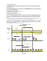
Page 4: ...1 4 7 2 3 0 2 9 1 4 6 1 4 0 1 41 1 Indication Zones Fault 1750msec LED Form 1a 2sec Duration of indication 2 250 msec Form 1b 1250msec 6 6 2 Duration of indication 2 sec Form 1c 6 Duration of indication Schematic 1 ...

Page 5: ... 41 1 41 0 1 0 1 1 1 2sec Indication Zones larm LED 6 4 5 6 4 5 250msec Zone in Alarm or Evacuate Duration of indication Schematic 2 8 6 A A 7 7 7 1 7 7 1 B CB3 1 1 1 2 3 0 1 1 1 1 1 6 A 3 1 41 6 1 1 1 1 1 6 A 3 1 1 1 1 1 6 A ...

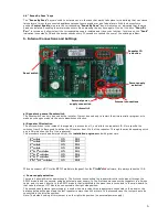
Page 6: ... When we connect a PC via the RS232 module to the panel for the 1 0 c 6 6 0 3 0 D D 0 D 7 E 8th switch ON ID 1 7th switch ON ID 2 6th switch ON ID 3 5th switch ON ID 4 8th 5th switches ON ID 5 7th 5th switches ON ID 6 6th 5th switches ON ID 7 8th 7th 5th switches ON ID 8 6 6 6 6 6 6 ...

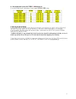
Page 7: ...Y Current in Standby Mode Current in Alarm Mode 4 27 6 V DC 2A 20mA 60mA 8 27 6 V DC 2A 20mA 75mA 12 27 6 V DC 2A 40mA 135mA 16 27 6 V DC 2A 40mA 150mA 20 27 6 V DC 2A 60mA 210mA 24 27 6 V DC 2A 60mA 225mA 7 F 1 0 6 F 6 3 6 3 G A B 6 6 C H 33 I ...

Reviews: