13
12
TOWER CONFIGURATION
The tower configuration allows the user to install the UPS in the up-right posi-
tion. The tower brackets are provided with the UPS.
WARNING:
Use two or
more people when installing the UPS, the UPS is extremely heavy.
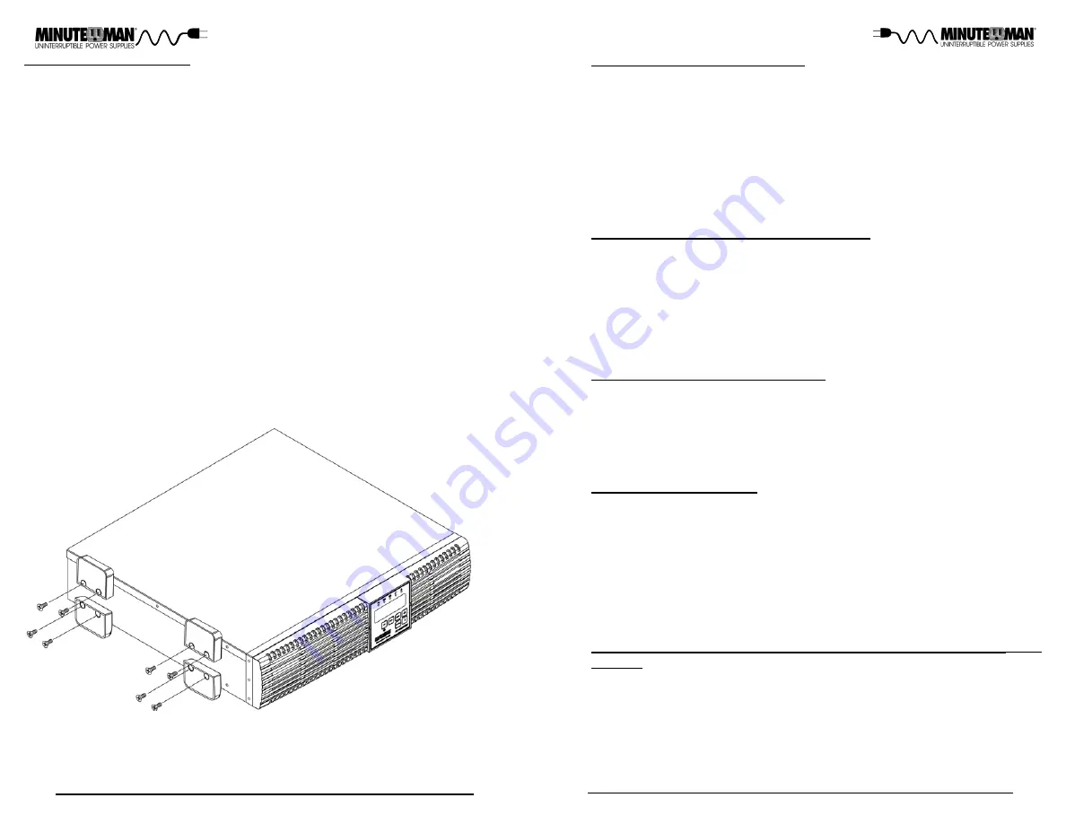
1. Once the location of the UPS has been determined, place the UPS on a flat
surface, remove the rackmount brackets from the UPS and then attach the
four (4) tower brakects as shown below.
2. Stand the UPS in the up-right position and place it in the desired location.
Make sure that the UPS is stable.
3. The LCD panel can be rotated to read in the up-right position. There are
two small slots, one on each side of the LCD panel. Insert a small flat scre-
wdriver into the slot to pop out the LCD panel. Position the LCD panel so
that it reads in the up-right position. Press the LCD panel back into the fr-
ont panel.
WARNING:
The UPS must be installed in the proper up-right position. If the
UPS is not installed in the proper up-right position the Batteries will be dam-
aged. Once the UPS is placed in the tower brackets, looking at the front panel
the YELLOW Battery disconnected label on the top cover of the UPS MUST be
on your left hand side.
4. The Tower Configuration is complete. See Connecting your Equipment.
CHARGING THE BATTERY
The UPS will charge the internal batteries whenever the UPS is connected to
an AC source and there is an acceptable AC voltage present (55V (load de-
pendent) - 150VAC). It is recommended that the UPS's batteries be charged
for a minimum of 4 hours before use. The UPS may be used immediately,
however, the “On-Battery” runtime may be less than normally expected.
NOTE:
If the UPS is going to be out of service or stored for a prolonged period of
time, the batteries must be recharged for at least twenty-four hours every
ninety days.
CHECKING THE SITE WIRING FAULT
After plugging the UPS into the AC wall outlet, check the Site Wiring Fault icon
on the front panel of the UPS. If the Site Wiring Fault icon is illuminated and
error code Er16 is displayed, the UPS is plugged into an improperly wired AC
wall outlet. If the UPS indicates a Site Wiring Fault have a Qualified Electri-
cian correct the problem.
CONNECTING THE UPS TO AN AC SOURCE
Plug the UPS into a two pole, three wire, grounded AC wall outlet. The AC wall
outlet shall be near the UPS and shall be easily accessible. The plug on the
input power cord on this UPS series is intended to serve as a disconnect
device. DO NOT PLUG THE UPS INTO EXTENSION CORDS, ADAPTER
PLUGS OR SURGE STRIPS. DO NOT CUT THE INPUT PLUG OFF AND
ATTEMPT TO HARDWIRE THIS UPS, DOING SO WILL VOID THE WAR-
RANTY.
NETWORK/PHONE/FAX/MODEM PROTECTION CONNECTION
(OP-
TIONAL)
Connect a 10/100/1000 Base-T network, single line phone, Fax or Modem line
to the RJ11/45 modular connectors on the rear panel of the UPS. This con-
nection will require another length of telephone or network cable. The cable
coming from the telephone service or networked system is connected to the
port marked “IN”. The equipment to be protected is connected to the port
marked "OUT".
NOTE:
Connecting to the Network/Phone/Fax/Modem modu-
lar connectors is optional. The UPS works properly without this connection.
CONNECTING YOUR EQUIPMENT
Plug the equipment into the output receptacles on the rear panel of the UPS.
Ensure that you do not exceed the maximum output rating of the UPS (refer to
the information label or the Electrical Specifications in this manual). DO NOT
PLUG EXTENSION CORDS, ADAPTER PLUGS OR SURGE STRIPS INTO
THE OUTPUT RECEPTACLES OF THE UPS.
CAUTION! DO NOT
connect a laser printer to the output receptacles on the
UPS, unless the UPS is rated 2000VA or greater. A laser printer draws signifi-
cantly more power when printing than at idle and may overload the UPS.


