


10
/12
Operating Instructions
8-channel light barrier multiplexer
IMX-N840
GB
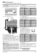
10. Check the supply voltage
On the right side of the multiplexer is the type plate. The
supply voltage is the last two or three numbers of the part
number. Check if this value is the same as the connection
value
.
IMX-N8X0 / 230VAC
type:
supply input: 230V AC
serial-no.: 000000
rev.: 1.0
supply voltage
e.g. 230 V AC
11. Operating procedure
Switch the power on. The green power indicator H11 (POWER
ON)
1
lights green. The information (interrupt or clearence
etc.) is evaluated and the state of the display and outputs are
shown. The displays H1 to H8 (RELAY-STATUS)
1
indicate
the state of the outputs. H12 to H19 (GAIN CONTROL)
1
indicate the state of the sensitivity.
To guarantee the right operation of the multiplexer, the
sensitivity of each channel must be adjusted manually.
Turn the potentiometer P1 (GAIN SETTING)
1
from the left
side to the right side until the green sensitivity indicator H12
(GAIN CONTROL)
1
is lit constantly (adjustment for channel
number one). Repeat the procedure for all channels. Should
the potentiometer further adjusted to the right side, the
multiplexer will become less sensitive. For description of
how the devices work, see
table 5
.
After adjustment the sensitivity indicator is an indicator for
the right adjustment. After a long working time the sensor
heads pollute and the sensitivity indicator is flashing and
goes out at further pollution. To get the optimum operation,
raise the sensitiviy or clean the sensor heads.
i
If the sensitivity indicator is not lit, the contact
between transmitter and receiver is interrupted or
the distance between the sensor heads is too far.
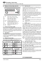
Beam status
Switch
mode
Output
status
indicator
H1 - H8
Output
Transmitter Receiver
light
dark
Transmitter Receiver
light
dark
table 5: Switching logic
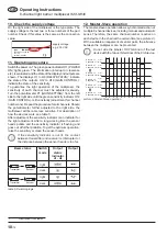
12. Master-Slave operation
The master-slave operation allows synchronized action of
multiple 8-channel devices, including manual and automatic
series. Therefore, the same channel number is active on
each device in the chain at the certain time (see
picture 4
).
With a suitable arrangement of sensor pairs, the influence
between the multiplexer can be prevented.
i
Do not wire the Master OUT terminal of the last
device with the Slave IN terminal of the first device.
Device No.1
Channel No.1
Device No.1
Channel No.2
Device No.1
Channel No.8
Device No.2
Channel No.1
Device No.2
Channel No.2
Device No.2
Channel No.8
t
t
t
t
t
t
active
inactive
active
inactive
active
inactive
active
inactive
active
inactive
active
inactive
picture 4: Master-Slave operation
1
Inscription front label