Panther Wall Spreader Instruction Manual Download Page 5


5.


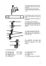
Once the entire Wall Spreader System has, with the aid of a helper, been 
placed at the desired height, pulled out to the required length and the clamping 
rings tightened, pressure can then be applied to the system. 


In order to do this, the two straining screws on both sides are tightened 
equally, thus forming the required arch upwards. 


A span A of 10m/33ft. should not be exceeded. Here, an arch with a 
height of approx. 40-45cm/17´´ is prescribed. Placing the load in the 
middle can increase the load capacity. 


The clamping ring connection must be really tight in order to take a maximum 
load of 75 kg/165 lbs in the middle of the arch. A span A of 6m/20ft. must not 
be exceeded in order to reach that payload. 


wall

A = 6 m/20ft.

max. 75 kg/165 lbs

B = ca. 35cm

       approx. 1ft.


6. 

The resulting arch on the Wall Spreader has to be braced. The struts are 
arranged using the double clamping ring. To support the struts on the wall, 
buffers are attached to the ends of the tubes. To be able to attach the struts 
free from play, the rubber buffers are unscrewed. Should a double clamping 
ring be placed on the thinner inside tube, the plastic sleeves have to be used 
to make up the difference in diameter. 


TIP:  When attaching heavy loads onto the system, it is recommended that 2 
clamping rings are attached one immediately after the other. 
 
Attention 

For human it is not allowed to hang up on or to stay below that 
spanning systems!


5

Summary of Contents for Wall Spreader

Page 1: ...W a l l S p r e a d e r Instruction Manual The Panther Telescopic Spanning System 1 ...

Page 2: ...g the actual dates or to book please contact 49 89 61390001 Repairs should only be carried out by the manufacturer or persons who received a special training Panther GmbH offers service seminars which can be held according to your desires Should you be interested please contact 49 89 61390030 Panther Service The PANTHER Wall Spreader may only be assembled according to this operating instruction Th...

Page 3: ...sed on plaster board insulating or hollow walls Only limited use on smooth or slippery surfaces Example Horizontal installation 1 Make a rough estimate of the spanning distance and begin assembly on the floor Be careful while doing so that objects do not get hit and injury is not coursed 2 Pull out the inside tube to the desired length and place a clamping ring where the inside tube joins to preve...

Page 4: ... too clamping ring outside tube inside tube Another method of spanning across larger distances is using an extension sleeve which joins the inside tubes of two telescopic poles inside tube extension sleeve 4 The spanning units are now fitted left and right the pressure plate placed horizontally facing downwards The two pressure screws have to be unscrewed before assembly 4 ...

Page 5: ...lbs in the middle of the arch A span A of 6m 20ft must not be exceeded in order to reach that payload wall A 6 m 20ft max 75 kg 165 lbs B ca 35cm approx 1ft 6 The resulting arch on the Wall Spreader has to be braced The struts are arranged using the double clamping ring To support the struts on the wall buffers are attached to the ends of the tubes To be able to attach the struts free from play th...

Page 6: ...vents the inside pole from sliding when the telescopic poles are arched The double clamping ring joins two poles which can cross at any given angle and which are supporting each other at the side The clamping ring with the euroadapter can be combined with Panther accessories e g bowl adapter Complete set existing of 2 pc telescopic pole 1 40 2 50 m 2 pc telescopic pole 2 15 4 00 m 2 pc telescopic ...

Reviews: