
INSTALLATION INSTRUCTIONS
© Panduit Corp. 2014
E-mail:
Phone:
866-405-6654
For Instructions in Local Languages
and Technical Support:
www.panduit.com/resources/install_maintain.asp
www.panduit.com
PN389B
Page 2 of 2
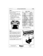
STEP 2
Identify conductor to appropriate signal
name per pinout table.
Due to the wide variety of video cable:
1. There is no standard color code for
the conductors other than the coaxial
Red, Green, and Blue.
2. The only certain way to identify
correct conductors is to perform a
continuity test.
3. There may be unused conductors for
your application.
PINOUT TABLE
PIN
SIGNAL
WIRE
1
2
3
*4
5
6
7
8
9
*10
*11
12
13
14
15
16
RED
GREEN
BLUE
ID BIT 2
GROUND
RED SHIELD
GREEN SHIELD
BLUE SHIELD
NO CONNECTION
SYNC RTN
ID BIT 0
ID BIT 1
HORZ SYNC
VERT SYNC
ID BIT 3
SHELL
COAX CC
COAX CC
COAX CC
TP
TP
COAX SHLD
COAX SHLD
COAX SHLD
N/C
TP
TP
TP
COND 1
COND 2
N/C
DRAIN WIRE
* Wires connected together
Greyed connections are optional
STEP 3
Before inserting wires for termination, turn
screws counter-clockwise to ensure all
clamps are completely open. (See Fig. 1)
Insert coaxial center conductors, coaxial
shields, and conductors into appropriate
slots of terminal board by signal name in
accordance with the pinout table.
Turn screws clockwise to ensure all clamps
are properly closed and wires are secure.
Fig. 1
HALF
CLOSED
OPEN
OPEN