background image

Basic Rack PDU User Manual

-

8

-

Installation

Before You Begin

Before installing your PDU, refer to the following lists to ensure that you have all the
items shipped with the unit as well as all other items required for proper installation.

Hardwire PDU installation instructions

This product is intended to be hardwired by the customer must be installed by a qualified
electrician AND adhere to all national & local electrical codes.

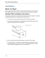
1. To install, remove the (4) securing screws on the removable user panel.

2. Unscrew strain relief grommet cap (indicated below) and feed the power cable

through the grommet cap & the input gland.

3. Ensure conductors are stripped adequately, exposing 15mm of copper.

4. Conductors shall be connected in-line with the terminal markings provided as

shown below (Line 1 = X; Line 2 = Y; Line 3 – Z). Ensure screws are secure for
each conductor by applying a torque of 2.3 N-m (20 in-lb.).

Summary of Contents for Basic Rack PDU

Page 1: ...Release 1 0 Issue 1 0 Panduit Basic Rack PDU User Manual...

Page 2: ...otocopying recording or otherwise without written permission from Panduit No patent liability is assumed with respect to the use of the information contained herein Although every precaution has been...

Page 3: ...sed 4 Equipment Overview 5 Model Numbering Format 5 Part Numbering Format 6 Pre Installation 7 Product Inspection 7 Installation 8 Before You Begin 8 Hardwire PDU installation instructions 8 Untermina...

Page 4: ...tribution system Contacting Panduit For technical support on PDU hardware and associated software please contact Pan duit Technical Support using one of the following methods l 1 866 721 5302 toll fre...

Page 5: ...e The cord and plug shall be rated for 20A in North America and 16A outside of North America Make the connection to the PDU before connecting to the power source Model Numbering Format This section de...

Page 6: ...ndicating input plug type and rated voltage E Any numeral 1 7 indicating the number of output circuit breakers F Any letter A Z indicating the type of overload protection provided for the outlets GH A...

Page 7: ...in EIA racks and cabinets Use of this product in other applications is acceptable but other pre cautions may be required to allow for specific installations not covered by this guideline Product Inspe...

Page 8: ...talled by a qualified electrician AND adhere to all national local electrical codes 1 To install remove the 4 securing screws on the removable user panel 2 Unscrew strain relief grommet cap indicated...

Page 9: ...re the grommet cap is torqued correctly Gland Size Grommet Cap Torque M16 1 5 N m 13 in lb M20 3 0 N m 27 in lb M25 4 0 N m 35 in lb M32 M40 15 N m 132 in lb M50 20 N m 177 in lb M63 30 N m 266 in lb...

Page 10: ...r to the matching phase in your facil ity Reference the color guide below Conductor Insulation Color Line Number Phase Brown Line1 X Black Line 2 Y Grey Line 3 Z Blue Neutral Green may include Yellow...

Reviews: