background image

AT-OMNI-512

21

Basic Configuration Tutorial

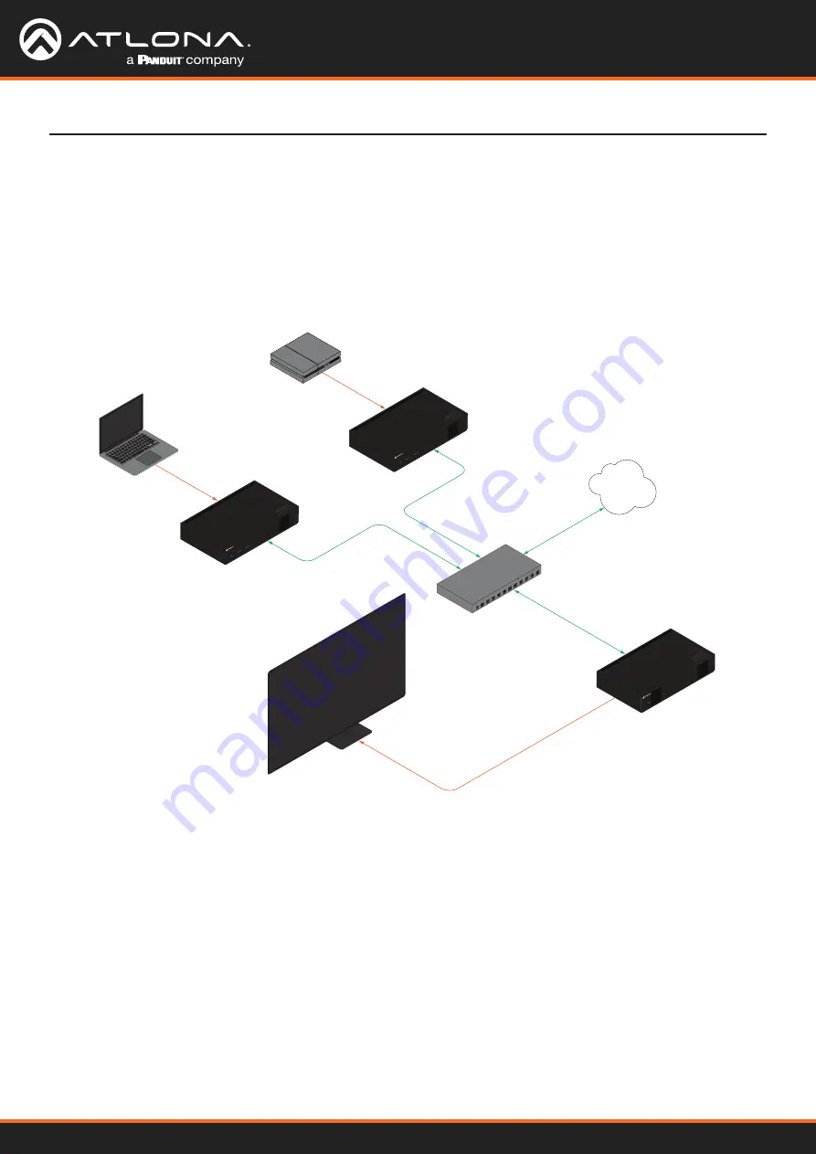
This section provides a tutorial on configuring two AT-OMNI-512 dual-channel encoders and one AT-OMNI-121 

single-channel decoder.  Make sure the encoder is connected to a source device and that the decoder is connected 

to a display.  Both the encoder and decoder should be connected to the same local network.  Refer t

Connection 

Instructions (page 15)

 for more information.

Physical Connections

AT-OMNI-512

AT-OMNI-121

PoE Network Switch

Laptop

Display

Ethernet

Ethernet

Ethernet

Ethernet

HDMI IN

LAN

HDMI OUT

AT-OMNI-512

HDMI IN

Gaming Console

Game Console

HD

MI

PW

R

LINK

TM

OMNI

STREAM

ID

1

2

1

2

R-T

YPE

HD

MI

PW

R

LINK

TM

OMNI

STREAM

ID

1

2

1

2

R-T

YPE

TM

OMNI

STREAM

LINK

PW

R

Encoder #1

Encoder #2

Decoder #1

Summary of Contents for Atlona OmniStream AT-OMNI-512

Page 1: ...AtlonaManuals NetworkedAV AT OMNI 512 Dual Channel Networked AV Encoder OmniStream R Type...

Page 2: ...AT OMNI 512 2 Version Information Version Release Date Notes 10 May 2023 Documentation typos corrected...

Page 3: ...ollowing link or QR code https atlona com warranty Main Office Atlona Incorporated 70 Daggett Drive San Jose CA 95134 United States Office 1 408 962 0515 Sales and Customer Service Hours Monday Friday...

Page 4: ...the following two conditions 1 this device may not cause harmful interference and 2 this device must accept any interference received including interference that may cause undesired operation This eq...

Page 5: ...16 Getting Started 17 Rebooting OmniStream 17 ID Button 17 Broadcast Messaging 17 Resetting to Factory Defaults 18 Using the ID button 18 Using the Mclear command 18 Using the Web Server 18 LED Indica...

Page 6: ...ding Slates Logos 54 Deleting Slates 55 Deleting Logos 55 Text Insertion 56 Configuring a Static IP Address 57 Configuration and Management Interfaces 58 Web Server 58 System information page 58 SAP L...

Page 7: ...s Package Contents 1 x AT OMNI 512 1 x 6 pin push spring connector 2 x Wall table mounting brackets 4 x Rubber feet Best in class AV over IP performance and reliability over Gigabit Ethernet AV encode...

Page 8: ...nected through a network switch As with all network devices both the encoder and decoder must have unique IP addresses OmniStream encoders and decoders are DHCP enabled by default This means that when...

Page 9: ...er lower latency and higher video fidelity than an interframe compression scheme such as H 264 or H 265 Interframe codecs are typically used by cable or internet providers and use very aggressive bit...

Page 10: ...ging the channel on a Set Top Box For example in order to view the content on channel 213 the Set Top Box must be set to channel 213 Similarly for a decoder to subscribe to an encoder stream the multi...

Page 11: ...d session will depend upon the encoder model The last three numbers of the OmniStream SKU describe the model version model type and number of inputs outputs The number of Ethernet ports and HDMI ports...

Page 12: ...t message to any network devices that are listening This button is also used to set the encoder to factory default settings Refer to ID Button page 17 for more information 5 Reboot button Press this b...

Page 13: ...cket 2 Remove at least 3 16 5 mm from the insulation of the RX TX and GND wires 3 Insert the TX RX and GND wires into correct terminal on the included push spring connector If using non tinned strande...

Page 14: ...is optional Either the top three or bottom three set of terminals can be used for IR Only the RS 232 2 port bottom set of connectors supports both RS 232 and IR Therefore this port must be used for I...

Page 15: ...to the RS 232 port on the decoder 4 IR optional Refer to IR Connections page 14 for wiring information IR emitter Connect the IR emitter to the TX and GND pins of the RS 232 2 port The IR emitter must...

Page 16: ...iagram Installation AT OMNI 121 E t h e r n e t E t h e r n e t PoE Network Switch E t h e r n e t LAN H D M I H D M I Display TM OMN ISTRE AM LIN K PW R ID Source AT OMNI 512 HD MI PW R LIN K TM OMN...

Page 17: ...ctory default settings Rebooting OmniStream HDMI PWR LINK TM OMNISTREAM ID 1 2 1 2 R TYPE AT OMNI 512 ETHERNET RS 232 IR DC 48V RX TX 1 2 HDMI IN 2 1 2 1 The ID button serves two functions 1 Sends a b...

Page 18: ...the encoder using the built in web server Refer to accessingwebserver for more information Note that OmniStream devices communicate using both LLDP and CDP protocols Consult the switch documentation...

Page 19: ...coder When using an external power supply the PWR indicator will be green Red The encoder is booting Amber The encoder is booting and or attempting to locate a DHCP server Green The encoder is ready H...

Page 20: ...commends downloading and using the Network Assignment Planner when setting up OmniStream products on the network Recording this information in this document will provide a snapshot of the current Omni...

Page 21: ...he encoder and decoder should be connected to the same local network Refer to Connection Instructions page 15 for more information Physical Connections AT OMNI 512 AT OMNI 121 PoE Network Switch Lapto...

Page 22: ...eam 2 0 features 1 2 3 Click SAVE at the bottom of the page to commit changes Login to the decoder interface and repeat this process Basic Configuration Tutorial Mode Description VCx This is the defau...

Page 23: ...ces are connected then try different HDMI cables If the HDMI cable integrity has been verified then make sure that the output resolution of the source is at least 720p 3 Click the EDID drop down list...

Page 24: ...R indicator is green this will indicate that HDR content is being transmitted from the source device Refer to the Input page page 62 for more information 7 The Audio section displays audio information...

Page 25: ...coding in the menu bar 2 Under the Encoder 1 window group click the Input drop down list and select hdmi_input1 3 Click the Bit depth drop down list to change the bit depth In this example it will be...

Page 26: ...scrambling by default Scrambling keys can be any combination of alphanumeric characters and it is good practice to use them For this tutorial use the default key 1 2 3 4 5 6 7 5 Click the Video Enable...

Page 27: ...abled When enabled it will be orange If disabled no audio will be streamed from the encoder 10 Enter the multicast IP address for the audio stream in the Destination IP address field Refer to Table 2...

Page 28: ...procedure for the Input 2 window group 3 Under the Input 1 window group enter 226 0 0 1 in the Multicast address field Under the Input 2 window group enter 226 0 0 2 in this field These multicast IP a...

Page 29: ...w groups These are the same port settings that were entered under the Audio UDP Port section of the encoder 4 Click the SAVE button under the Input 3 and Input 4 window groups to commit changes 1 2 3...

Page 30: ...etting 4 Click the HDCP Version drop down list and select the HDCP version 2 2 will work with most sources However in this case an older sink monitor which doesn t support HDCP 2 2 is being used There...

Page 31: ...Audio 226 0 10 1 1100 Input Multicast Address Port Input 2 Video 226 0 0 2 1000 Input 4 Audio 226 0 10 2 1100 Encoder 1 Encoder 2 The decoder should now display the content of the source device connec...

Page 32: ...ID 1 2 1 2 R TYP E HD MI PW R LIN K TM OMN ISTRE AM ID 1 2 1 2 R TYP E TM OMN ISTR EA M LIN K PW R Session 1 Session 1 Destination IP Address Video 226 0 0 1 UDP Port Video 1000 Destination IP Address...

Page 33: ...ups Refer to Creating a Session page 26 for more information Check that the Scrambling Enable toggle switch is enabled Also check that the Scrambling Key field for this example is set to scrambling Ve...

Page 34: ...address In this example 226 0 10 1 for Input 3 and 226 0 10 2 for Input 4 Check that the Port field is set to 1100 for both Input 3 and Input 4 Go to the HDMI Output menu and verify the following Ref...

Page 35: ...tton within the Input window group to commit changes EDID Management OmniStream encoders provide EDID management for each input The encoder can be assigned one of several included EDID presets or can...

Page 36: ...uded 6 Click the CREATE button to commit changes or click CANCEL to abort the addition of a custom EDID Once a custom EDID is loaded it will be added to the drop down list and can be selected without...

Page 37: ...ress of a display or a decoder Downstream Control using RS 232 1 Login to the encoder and click the Serial menu 2 Under the Serial Port Configuration window group click the Mode drop down list and sel...

Page 38: ...desired serial port 8 Click the Enable toggle switch to display the additional fields 9 Enter the destination IP address and UDP port in the Destination IP address and Destination UDP port fields res...

Page 39: ...s was used in Step 9 then that multicast address must be entered in the Multicast address field under Input 5 13 Click the Enable toggle switch to enable the Input When an Input is enabled the toggle...

Page 40: ...P traffic received by an encoder or decoder on the defined IP Port socket are translated to RS 232 allowing both control of source or display Control is achieved using a control system where all contr...

Page 41: ...he Port drop down list and select the desired serial port 5 Click the Mode drop down list and select tcpproxy 6 Click the TCPProxy Interface drop down list and select the desired Ethernet interface 7...

Page 42: ...1 Login to the decoder and click the Serial menu 2 Under the Serial Port Configuration window group for the desired serial port click the Mode drop down list and select Serial 3 Click the SAVE button...

Page 43: ...Off Volume Up and Volume Down 9 Enter the command data in either ASCII or hexadecimal format using the ASCII or HEX fields 10 Click the SAVE button 8 9 9 10 11 Open a Telnet SSH session with the deco...

Page 44: ...ist and select decoder The available commands are Display On Display Off Volume Up and Volume Down NOTE Setting the Interpret on drop down list to encoder implies that commands are defined stored on t...

Page 45: ...hen an Input is enabled the toggle switch will be orange 12 Enter the UDP port from Step 8 in the Port field 13 Click the SAVE button 5 6 7 8 8 9 5 Click the Session menu 6 Under the desired Session l...

Page 46: ...ick the Mode drop down list and select output 14 15 16 18 17 19 19 Click the SAVE button 20 Open a Telnet SSH session with the encoder and trigger display control using any of the following commands I...

Page 47: ...k the Serial menu 2 Under the Serial Port Configuration window group click the Mode drop down list and select Serial 3 Click the SAVE button 4 Under the Serial configuration window group click the Por...

Page 48: ...Under the Serial Port Configuration window group click the Mode drop down list and select Serial 13 Click the SAVE button 14 Under the Serial configuration window group click the Port drop down list...

Page 49: ...g IR To control of headend source from downstream refer to the Upstream Control using RS 232 page 47 instructions Once configured make sure that the serial port is configured for infrared as shown inf...

Page 50: ...as Dolby Digital and others Source audio must be transmitted as LPCM up to eight channels at 192 kHz 24 bit 1 Login to the encoder and click Session in the menu bar 2 Click the SAP Enable toggle switc...

Page 51: ...AP listener When enabled the toggle switch will be orange 7 Click the SAVE button 8 Click the IP Input menu 9 Select the desired IP input for AES67 audio and click the Enable toggle switch When enable...

Page 52: ...Output menu 13 Locate the Audio section click the Audio Input drop down list and select the input that was configured in Steps 10 and 11 14 Click the Enable AES67 toggle switch to enable it When enab...

Page 53: ...he default scrambling key is scrambling Scrambling 1 Login to the encoder 2 Click Session in the menu bar 3 Locate the Scrambling section under the desired Session window group 4 Click the Enable togg...

Page 54: ...Click the Choose File button and select the desired image Only png or svg files are valid selections 5 Click the UPLOAD button to upload the file 6 A new window group will be created with the name of...

Page 55: ...if enabled to disable the feature 3 Click the SAVE button at the bottom of the window group to commit changes 4 Click the DELETE button for the logo to be removed Slate mode Description Off Disables...

Page 56: ...ed Green and Blue fields can be changed to further modify the color of the text Adjust the Alpha field to control the transparency of the text A value of 255 is opaque and a value of 0 is transparent...

Page 57: ...ill be used to assign the encoder an address within the IPv4 address block 169 254 xxx xxx 16 If this occurs connect an Ethernet cable directly from the ETHERNET port of the encoder to the LAN port of...

Page 58: ...This is the default mode and represents the latest codec technology from Atlona with outstanding support for computer graphics and motion video VCx includes support for 4K60 4 4 4 fast switching dual...

Page 59: ...ower consumption of the encoder Hostname Displays the hostname of the encoder By default OmniStream encoders are assigned a default hostname which is constructed as follows at omni SKU last five digit...

Page 60: ...not work for multiple encoders on the same network FACTORY RESET Click this button to reset the encoder to factory default settings When performing a factory reset the following options can be selecte...

Page 61: ...cement is picked up it will be displayed below the SAP window group as shown here Addresses Encoders currently send SAP announcements on two multicast addresses 224 2 127 254 and 239 255 255 255 These...

Page 62: ...DID Description Default HDR MCH Default EDID with HDR 3840x2160p30 and multichannel audio Default HDR 2CH Default EDID with HDR 3840x2160p30 and two channel audio Default DV MCH Default EDID with Dolb...

Page 63: ...select the version of HDCP to be supported 2 2 1 4 or None Negotiated Version This field displays the HDCP version that has been negotiated with the source The following fields will only be displayed...

Page 64: ...th Available values are 8 10 and 12 Colorspace Displays the color depth Framerate Click in this field to change the frame rate in Hz of the video generator signal The default value is 60 Subsampling D...

Page 65: ...rred mode Displays the preferred timing and resolution of the EDID This field cannot be changed Supported modes Mode In addition to the preferred timing and resolution each EDID structure contains a l...

Page 66: ...lick this drop down list to select the input Available options are not used hdmi_input1 and video_ generator1 For Encoder 2 the options are not used hdmi_input2 and video_generator2 Max bit rate This...

Page 67: ...for displaying system instructions when no sources are connected Slate logo Click this drop down list to select the desired slate logo Thumbnail Enable Click this toggle switch to enable to disable a...

Page 68: ...oth Serial port configuration window groups Mode Click this drop down list to select the desired serial mode Available values will be reflected in the Supported Modes field Baudrate Click this drop do...

Page 69: ...is button to create a new command window group Provide a name for the command in the displayed dialog box then click the Create button Complete each of the fields as described above Mode Click this dr...

Page 70: ...page Session window groups The following fields apply to all Session window groups The AT OMNI 512 supports up to four sessions Name The name of the session This field cannot be changed Interface The...

Page 71: ...d must contain a minimum of eight characters Special characters and spaces are not permitted Scrambling Video Encoder Click this drop down list to select the encoder input Enable Click this toggle swi...

Page 72: ...n the encoder are sent to the decoder serial port Refer to Downstream Control using Triggering page 42 for more information Serial Port 1 Commands are transmitted using Serial Port 1 Serial Port 2 Com...

Page 73: ...AT OMNI 512 73 Configuration and Management Interfaces Listen port Enter the listening port in this field SAVE Click this button to commit all changes within the Session window group...

Page 74: ...ear in the Logo drop down list UPLOAD Click this button to upload the logo file to the encoder New logo window group Logo Insertion window groups The following fields apply to both Logo Insertion wind...

Page 75: ...the resolution of the video stream Vertical Enter the vertical position of the logo based on the resolution of the video stream Width Enter the width of the logo This value is based on the horizontal...

Page 76: ...text from right to left Iterations Enter the number of iterations in the Iteration field Set this field to 0 zero to set the number of iterations to infinity Color Click this drop down list to select...

Page 77: ...the vertical position of the text based on the resolution of the video stream Width Enter the width of the text This value is based on the horizontal resolution of the video stream Height Enter the he...

Page 78: ...desired IP mode Select DHCP to let the DHCP server if present assign the encoder the IP settings When static is selected the information for the IP Address Subnetmask and Gateway fields must be entere...

Page 79: ...Click this toggle switch to enable or disable Telnet authentication If enabled then the toggle switch will be orange Once enabled connecting to the encoder using Telnet will require login credentials...

Page 80: ...utage will be experienced while all connected devices synchronize with the new clock Because of this Atlona recommends that one unit gets manually defined as the GM and have both Priority 1 and Priori...

Page 81: ...s the TTL value The default IPV4 TTL value used for PTP is 8 Is GM If the indicator is green then this interface is the PTP GM GM Identity The grandmaster clock identity Master Offset Displays the gra...

Page 82: ...eing used RID The router ID Age Up time of the interface Chassis ID The MAC address of the interface Chassis Capability Indicates the device function such as bridge switch router etc NOTE LLDP must be...

Page 83: ...e hostname specific to the configuration filename will be ignored EXPORT Click this button to export the current encoder system configuration to a json file Choose File Click these buttons to select t...

Page 84: ...this button to delete the user in the current window group Note that the at least one admin role must exist at all times Therefore if one admin role and one operator role exist then the admin user ca...

Page 85: ...tion and Management Interfaces License Key Enter the license key in this field INSTALL LICENSE Click this button to validate and install the license This page displays all installed licenses and allow...

Page 86: ...onfiguration and Management Interfaces Choose File Click this button to select the firmware file to be uploaded UPLOAD Click this button to upload the selected firmware file This page is used to updat...

Page 87: ...de in the menu bar to display the Upgrade page 5 Click the Choose File button 6 In the Open dialog box select the correct firmware file Refer to the table below 7 Click the UPLOAD button 8 A progress...

Page 88: ...ddress of the subscribing decoder in the address bar 3 Verify that all desired decoders are subscribed to the encoder s multicast address and port number In the decoder example below the IP Input Inpu...

Page 89: ...test the encoder web page will automatically redirect to the Notifications tab where the user can see the results Appendix If the test passed information similar to the following will be displayed Not...

Page 90: ...ss Hovering the mouse over the Description field will provide the full IP address of each decoder which received the test as shown below If multiple decoders were tested additional IP addresses will b...

Page 91: ...sure 4 To provide added stability to the rack ear use two of the included screws and attach them to the two holes directly below the enclosure screws as shown above 5 Repeat steps 1 through 4 to attac...

Page 92: ...k tray The OmniStream rack tray can be purchased directly from Atlona 1 Position the OmniStream products as shown in the illustration below 2 Using the included screws secure each unit to the rack wit...

Page 93: ...bsampling Chroma VCx VC 2 Video 4 4 4 Yes No 4 2 2 Yes No 4 2 0 Yes Yes Color Depth 8 bit 10 bit 12 bit HDR HDR10 HLG Dolby Vision Bit Rate Configurable up to 900 Mbps Latency 0 5 frame e g 1080p 60 H...

Page 94: ...ics Features Text Insertion Adjustable height width scrolling speed direction or static iterations up to infi nite positioning and adjustable color and alpha transparency channels Slate Logo Insertion...

Page 95: ...ting Humidity RH 20 to 95 non condensing Maximum Operating Altitude 2000 meters Cooling System Front to rear airflow temperature controlled fans Footnotes 1 Interlaced sources are passed through witho...

Page 96: ...US International atlona com 408 962 0515 41 43 508 4321 35207 R10...

Reviews: