


6
Installation Guide
AT-OMNI-311
LINK
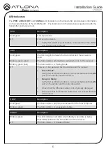
Description
Solid green
The link integrity between the transmitter and the receiver is
good.
Blinking green (slow)
The transmitter is attempting to establish a link to the receiver.
Blinking green (fast)
The transmitter is in Pairing Mode.
Off
There is no link between the transmitter and the receiver.
•
Direct Mode:
Verify that an Ethernet cable is connected between the
LAN
port on the sender and the receiver.
•
Network Mode:
Verify that an Ethernet cable is connected between the
LAN
port on the sender and the network switch.
•
Check that the Ethernet cable is not physically damaged.
•
Make sure that the Ethernet cable does not exceed 330 feet
(100 meters).
HOST
Description
Solid green
The transmitter is properly enumerated on the host computer.
Blinking green
The transmitter is in a suspended state.
SIGNAL
Description
Blinking green
This LED indicator will blink intermittently when data is being
transmitted between the transmitter and the receiver.
Off
The transmitter is in Suspend Mode.
PWR
Description
Solid green
Unit is powered.
Off
Unit is not powered.
•
Verify that a USB Type-B cable is connected from the HOST
port to the host computer.
LED Indicators
The
PWR
,
LINK
,
HOST
, and
SIGNAL
LED indicators on the transmitter provide basic information
on the current status of the AT-OMNI-311. The information in the table below applies to both the
transmitter and receiver unit.


