background image

AT-OMNI-111 / AT-OMNI-112

69

Advanced Operation

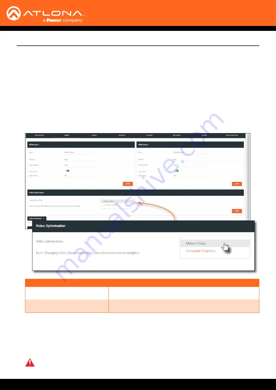
OmniStream offers two video modes:  Video and PC application.  These two modes will optimize the video, based on 

the type of information that is being displayed.   Use the 

Video

 mode when display motion graphics/video.  Set this 

mode to 

PC application

 when viewing static images, such as spreadsheets or similar content.

Setting the Video Mode

1. 

Login to AMS.  Refer to 

Accessing Encoders in AMS (page 16)

, if necessary.

2.  Click 

INPUT

 in the menu bar.

3.  Click the 

SHOW ADVANCED

 button, under the 

HDMI Input 1

 window group.

4.  Click the 

Video Optimization 

drop-down list to select the desired mode.

4.  Click the 

SAVE

 button, within the 

Video Optimization

 window group to commit changes.  Note that switching 

between video modes may take a few moments to complete.

5.  Go to the decoder interface and repeat the process.  Refer to the 

OmniStream Single-Channel / Dual Channel 

A/V Decoder User Manual

, if necessary.

Mode

Description

Computer Graphics

Optimizes the image when viewing static images, such as 

spreadsheets or similar content.

Motion Video

Provides the best viewing experience when streaming motion graphics 

and/or video.

IMPORTANT:

  In order to use 3840x2160p60 signals, 

Video Optimization

 must be set to 

Motion 

Video

.

Summary of Contents for Atlona OmniStream AT-OMNI-111

Page 1: ...AtlonaManuals NetworkedAV AT OMNI 111 AT OMNI 112 Single Channel Dual Channel Networked AV Encoder OmniStream...

Page 2: ...dded EDID management text insertion state logo insertion encoder grouping 4 May 2018 Updated to reflect AMS 2 0 5 Jun 2018 Includes updates to 1 2 1 firmware AMS updates 6 Jan 2019 1 2 2 firmware enco...

Page 3: ...come to Atlona Operating Notes IMPORTANT Visit http www atlona com product AT OMNI 111 and http www atlona com product AT OMNI 112 for the latest firmware updates and User Manual Main Office Atlona In...

Page 4: ...d Product Warranty Terms New Products 10 years from proof of purchase date for hardware electronics products purchased on or after June 1 2013 3 years from proof of purchase date for hardware electron...

Page 5: ...stricts or states do not allow the exclusion or limitation of relief special incidental consequential or indirect damages or the limitation of liability to specified amounts so the above limitations o...

Page 6: ...ions 5 Do not use this product near water 6 Clean only with a dry cloth 7 Do not block any ventilation openings Install in accordance with the manufacturer s instructions 8 Do not install or place thi...

Page 7: ...t Mode 26 ID Button 27 Broadcast Messaging 27 Reset to Factory Default Settings 27 Input Switching Configuration 28 Unicast Mode 29 Multicast Mode 31 IR Control 33 Controlling the Display using the Di...

Page 8: ...Logos 70 Deleting Slates Logos 73 Text Insertion 74 The AMS Interface 75 Device Info page 75 Input page 78 Serial page 81 Session page 83 Network page 86 Other page 88 Logo 88 Text 89 PTP 90 The Virtu...

Page 9: ...pendability of traditional AV distribution with the virtually unlimited scalability and cost efficiency of integrating over data networks It addresses the many challenges AV and IT integrators encount...

Page 10: ...REBOOT Use a small pointed object to press this recessed button and reboot the unit 6 HDMI Connect an HDMI cable from this port to an HD source 7 ETHERNET Connect an Ethernet cable from this port to...

Page 11: ...E Press these buttons to adjust the output volume of the desired display Refer to Adjusting Volume page 26 for more information 7 ID This button provides two functions 1 Press and release this button...

Page 12: ...GND connections Push tab to unlock GND RX TX RS 232 Connections External Power Optional NOTE Typical DB9 connectors use pin 2 for TX pin 3 for RX and pin 5 for ground On some devices pins 2 and 3 are...

Page 13: ...the decoder endpoint This step is optional IR control is only supported on RS 232 2 port bottom set of connectors Refer to IR Control page 33 for configuration details IR emitter configuration IR ext...

Page 14: ...der 4 IR optional IR emitter Connect the IR emitter to the TX and GND pins of the RS 232 2 port The IR emitter must be placed no more than 1 from the IR sensor on the device in order to function prope...

Page 15: ...S PLA Y INP UT ID 1 2 1 2 1 2 ID PW R LIN K TM OMN ISTRE AM R S 2 3 2 C o n t r o l R S 2 3 2 C o n t r o l Ethernet PoE Ethernet LAN 2 COM NC NO COM NC NO COM NC NO COM NC NO 12V SIG GND 12V SIG GND...

Page 16: ...he network Note that AMS will only be able to discover encoders if they are on the same VLAN In order for AMS to automatically assign multicast IP addresses to OmniStream encoders the destination IP a...

Page 17: ...NI 112 17 6 Click Devices from the fly out menu Configuration Arrow buttons 7 Click the Unassigned option 8 Click the left and right arrows at the bottom of the Unassigned list to scroll through all a...

Page 18: ...cated on the same subnet 169 254 xxx xxx subnet mask 255 255 0 0 Refer to Configuring a Static IP Address page 20 for more information on configuring an encoder in Auto IP mode If no OmniStream encode...

Page 19: ...o section and delete the value in the Destination Multicast Unicast Address field SAVE button Destination Multicast Unicast Address field 15 Scroll down to the bottom of the page and click the SAVE bu...

Page 20: ...tly to one of the Ethernet ports on the encoder Make sure that the computer being used has AMS installed 3 Configure the PC to a static IP address that is on the same subnet as the encoder 4 Login to...

Page 21: ...egabits per second Mbps 4K UHD streams should be set to 900 Mbps The recommended bandwidth for 1080p60 video is also 450 Mbps Setting this field below these recommended values will result in lower qua...

Page 22: ...integrity of the cable if the cable is bad or does not maintain a secure connection then the Cable Present indicator may also be displayed as red If this is the case try a different HDMI cable Dual c...

Page 23: ...re that the Enable Video toggle switch is enabled green To disable video at any time click the toggle switch so that it appears gray 5 Enter the destination multicast IP address in the Destination Mul...

Page 24: ...upply available from atlona com to the encoder When using an external power supply the PWR indicator will be red Red The encoder is booting Green The encoder is ready HDMI 1 2 Red No source is connect...

Page 25: ...live This will allow connected devices such as laptop computers to remain in presentation mode and not revert to single screen mode After the input is selected AMS will require configuration Refer to...

Page 26: ...ired press and release the INPUT button Press the desired VOLUME control button to immediately change the volume on the display Depending upon the output mode of the encoder the VOLUME buttons will be...

Page 27: ...ry default settings ID Button Basic Operation Press and release the ID button to send a broadcast notification over the network to any devices that may be listening 1 Press and hold the ID button for...

Page 28: ...age 16 if necessary 3 Click SESSION in the menu bar 4 Under the Stream 2 window group click the Encoder drop down list and select Not Used It should be noted that Not Used could have been set under St...

Page 29: ...M OMN ISTRE AM VO LUM E DIS PLA Y INP UT ID 1 2 1 2 HD MI PW R LIN K TM OMN ISTRE AM VO LUM E DIS PLA Y INP UT ID 1 2 1 2 HD MI PW R LIN K TM OMN ISTRE AM VO LUM E DIS PLA Y INP UT ID 1 2 1 2 LAN 192...

Page 30: ...A V Decoder User Manual if necessary 6 Click IP INPUT from the menu 7 Remove the IP address from the Multicast Address field 8 Click the SAVE button to commit changes 9 Unicast setup is complete The d...

Page 31: ...AMS Dashboard will be displayed 3 Click the icon in the upper left corner of the AMS Dashboard 4 Click Virtual Matrix from the fly out menu Refer to The Virtual Matrix page 92 if necessary 5 Locate th...

Page 32: ...AT OMNI 111 AT OMNI 112 32 Basic Operation...

Page 33: ...ontrolling the Display using the Display s IR Remote Controlling the Display using a Control System The illustration below shows a display device being controlled from the encoder Refer to the next pa...

Page 34: ...tors on the Xantech 789 44 4 Source Connecting Block using a regular screwdriver and connect the SIGNAL GROUND and POWER leads of the AT IR CS RX to the Xantech 789 44 4 Source Connecting Block as sho...

Page 35: ...he illustration below for purposes of clarity Connecting the IR Emitter to the Decoder 1 Connect the included 6 pin Phoenix connector to the RS 232 2 port on the encoder 2 Connect the SIGNAL wire of t...

Page 36: ...e admin Password Atlona 3 Click the Login button 4 The AMS Dashboard will be displayed 5 Click the icon in the upper left corner of the AMS Dashboard 6 Click Devices from the fly out menu 7 Click the...

Page 37: ...Serial page of the encoder web interface 1 Enter the IP address of the encoder in the address bar of the web browser 2 Enter the required login credentials The default login is Username admin Password...

Page 38: ...so be used with IR However in this example Session 1 will be configured 1 Click SESSION in the top menu bar 2 Locate the Session 1 window group Configuring the Encoder Session The next step is to assi...

Page 39: ...clicking the Enable toggle switch When the auxiliary channel is enabled this toggle switch will be orange 6 Enter the IP address of the decoder in the Destination IP Address field This is the decoder...

Page 40: ...5 by clicking the Enable toggle switch When enabled this toggle switch will be orange 6 Enter the port in the Port field This port number must be the same port used by the encoder and is the input of...

Page 41: ...ort2 Click the Modes drop down list and select Infrared 10 Click the SAVE button to commit changes 11 Scroll down the page and locate the Serial Configuration window group The Name field within this g...

Page 42: ...AT OMNI 111 AT OMNI 112 42 15 Click the SAVE button to commit changes IR Control...

Page 43: ...RTANT The IR lens of the emitter must be within 1 inch 2 54 centimeters of the IR window on the display device If this distance is exceeded then IR functionality may fail 1 Point IR remote to at the I...

Page 44: ...should be used instead of an IR receiver as shown below AT OMNI 111 Network Switch AT OMNI 121 Control System Ethernet Ethernet H D M I IR HDMI Display IR Emitter HD MI PW R LIN K TM OMN ISTR EA M VO...

Page 45: ...sing the Virtual Matrix 1 Login to AMS Refer to Accessing Encoders in AMS page 16 if necessary 2 Click the icon in the upper left corner of the AMS Dashboard 3 Click on Virtual Matrix 4 The OmniStream...

Page 46: ...and select Control IR Control 6 The Control screen will be displayed In the Control screen HDMI ports are replaced with control ports Port 1 In Port 1 In for encoders and Port 1 Out Port 2 Out for de...

Page 47: ...al Port 2 supports IR pass through The IR emitter or IR receiver must be connected to this port Refer to RS 232 Connections page 12 for wiring information 10 Click SAVE to commit changes then click CL...

Page 48: ...bits and flow control settings as required by the connected device These settings can be changed in the Serial Port section under the SERIAL menu Using TCP Proxy This method is used to send IP comman...

Page 49: ...l Matrix 1 Login to AMS Refer to Accessing Encoders in AMS page 16 if necessary 2 Click the icon in the upper left corner of the AMS Dashboard 3 Click on Virtual Matrix 4 The OmniStream Virtual Matrix...

Page 50: ...select Control Advanced Operation 6 The Control screen will be displayed In the Control screen HDMI ports are replaced with control ports Port 1 In Port 1 In for encoders and Port 1 Out Port 2 Out fo...

Page 51: ...Refer to the list of modes on the right hand side of the dialog for a description of each The table below provides a summary of serial port control methods available for each encoder decoder Orange c...

Page 52: ...to the decoder The RS 232 commands are then received by a display DCE device or other sink device 1 Select RS232 Passthrough from the Serial Mode drop down list 2 Click SAVE to commit changes then cli...

Page 53: ...e the required settings These settings must match the port settings on the display sink device a Click the Interface drop down list to select the interface Ethernet port that will be used to transmit...

Page 54: ...able on both the OmniStream encoder and decoder Ethernet EAPOL EAP EAP Ethernet RADIUS Ethernet Normal tra c Supplicant Encoder or Decoder Authenticator Switch Extensible Authentication Protocol Authe...

Page 55: ...ethod In the example below PEAP MSCHAPv2 is selected 6 Once a method is selected the required fields for that method will be displayed Enter the required information in each field For the PEAP MSCHAPv...

Page 56: ...s An orange dot indicates that this field will be displayed as part of the method Authentication Method Identity Password CA Certificate CA Certificate Client Private Certificate PEAP MSCHAPv2 EAP TLS...

Page 57: ...Locate the Audio section under the desired Stream and click the Enable AES67 toggle switch to enable this feature When enabled the toggle switch will be green 5 Select the type of downmixing from the...

Page 58: ...e EDID Name field Spaces and special character are valid entries Use a descriptive name for this field 4 Click the SAVE button to commit changes EDID Management OmniStream encoders provide EDID manage...

Page 59: ...Note that the available EDID selections will depend upon the current video mode Refer to Setting the Video Mode page 69 for more information Common EDID 2CH LPCM MCH LPCM DTS Dolby Dolby Digital DTS H...

Page 60: ...tal Plus or Dolby True HD audio streams DTS X is carried with DTS HD MA audio streams 1 Login to AMS and access the desired decoder Refer to Accessing Encoders in AMS page 16 except instead of clickin...

Page 61: ...nd select the data in this field then press CTRL C to copy the data Advanced Operation Display s EDID 5 Select the desired encoder within AMS 6 Click INPUT in the menu bar 7 Click the EDID drop down l...

Page 62: ...ntries Use a descriptive name for this field 10 Paste the EDID data into the Raw EDID field by pressing CTRL P 11 Click the SUBMIT button to commit changes or click CANCEL to abort the addition of the...

Page 63: ...multaneously The stream will be displayed by the decoder using either manual or automatic input selection based on the presence of a source signal Advanced Operation Group Name Encoder IP address 5 Un...

Page 64: ...y enable the input When set to manual click the Activate button to perform the input switching input connected Use this setting to allow the encoder group to use automatic input detection Once a new s...

Page 65: ...V 0 83 A DC 48V 0 83 A DC 48V 0 83 A DC IMPORTANT The optional OmniStream power supply AT PS 48083 C must be connected to each encoder that is daisy chained in order to supply the required power Note...

Page 66: ...s multicast IP address in order to display the content Daisy chained encoders can only display one source at a time Click the Trigger drop down list to determine how the encoder will handle switching...

Page 67: ...Data streams cannot be scrambled By default scrambling is disabled Scrambling 1 Login to AMS Refer to Accessing Encoders in AMS page 16 if necessary 2 Click SESSION in the menu bar 3 Under the desired...

Page 68: ...l be displayed If the key icon for a decoder is clicked then the Descrambling dialog box will be displayed 4 Click the Enable toggle switch to enable scrambling for the desired session Key icon 5 Ente...

Page 69: ...r the HDMI Input 1 window group 4 Click the Video Optimization drop down list to select the desired mode 4 Click the SAVE button within the Video Optimization window group to commit changes Note that...

Page 70: ...the image is unique to the specified HDMI output Refer to the OmniStream Single Channel Dual Channel A V Decoder User Manual for information on managing slate logo insertion on decoder units 1 Login t...

Page 71: ...then proceed with Steps 9 through 13 If the image will be used as a slate skip to Step 14 9 Under the HDMI Input Logo window group click the Select Logo drop down list and select the desired logo To p...

Page 72: ...s 14 Click INPUT in the menu bar then click the SHOW ADVANCED button 15 Click the Slate mode drop down list and select Off Manual or Auto 16 Click the Slate Logo drop down list and select the desired...

Page 73: ...oup and the associated image will be deleted from the encoder If the DELETE button is disabled do the following a Locate the HDMI Input Logo window groups b Click the Select Logo drop down list and se...

Page 74: ...Iteration field Set this field to 0 zero to set the number of iterations to infinity 7 Click the Color drop down list to select the color of the text The Red Green and Blue fields can be changed to fu...

Page 75: ...ription AT OMNI 111 Single channel encoder AT OMNI 112 Dual channel encoder IP Address Displays the IP address of the encoder MAC Address Displays the MAC address of the encoder Firmware version The v...

Page 76: ...e following options can be selected by clicking the check box If no options are selected then the encoder is reset with no factory default settings Option Description None Checked Resets the encoder w...

Page 77: ...ver in this field This provides timestamps for any logs and alarms Buttons Disabling this feature will lock the ID button on the front panel This feature is enabled by default LEDs Disabling this feat...

Page 78: ...ing Click this drop down list to select the desired maximum chroma subsampling value Any input with a higher chroma subsampling will have their chroma scaled to the configured value using a very high...

Page 79: ...3840x2160p30 with multichannel PCM audio ATL 2560x1600 2CH 2560x1600p60 with two channel PCM audio ATL 2560x1600 MCH 2560x1600p60 with multichannel PCM audio ATL 4K60 MCH 3840x2160p60 with multichanne...

Page 80: ...late mode or select the desired slate to be used Refer to Slate Logo Insertion page 70 for more information Video Optimization Sets the output video mode Refer to Setting the Video Mode page 69 for mo...

Page 81: ...9600 19200 38400 57600 or 115200 Data Bit Click this drop down list to select the number of data bits 6 7 or 8 Parity Click this drop down list to select the parity bit None Odd Even Mark or Space St...

Page 82: ...t on Description decoder Commands are interpreted at the decoder encoder Commands are interpreted at the encoder NOTE When entering the command string it is not required to enter the string under both...

Page 83: ...terface Interface Description eth1 ETHERNET 1 port eth2 ETHERNET 2 port SAP Click this switch to enable to disable the Session Announcement Protocol When enabled the toggle switch will be green Scramb...

Page 84: ...st IP addresses for the encoder Destination UDP Port Enter the destination UDP port in this field TTL Set the TTL Time To Live duration from 1 to 255 seconds in this field The default value is 255 sec...

Page 85: ...o be unreliable due to noise or other factors By default this feature is enabled Refer to FEC Details page 97 for more information FEC rows Specify the number of FEC rows in this field Refer to FEC De...

Page 86: ...is indicator is green then an active link exists Otherwise if no link exists this indicator will be red DHCP Mode Click this drop down list to select the desired network mode Select DHCP to let the DH...

Page 87: ...ion Click this toggle switch to enable or disable Telnet authentication If enabled then the toggle switch will be green Once enbled connecting to the encoder using Telnet will require login credential...

Page 88: ...ile Click this button to select the logo file to be uploaded Files must be in png format and must not exceed 5 MB 5120000 bytes in size When an image file is uploaded it will appear in the Logo drop d...

Page 89: ...or disable the text When the toggle switch is green the text will be enabled Text Enter the desired text in this field Scroll Speed Enter the scrolling speed in this field Values from 255 to 255 are v...

Page 90: ...f these fields The AMS Interface Click the SHOW ADVANCED button to view the following options The PTP page provides options for adjust Precision Time Protocol PTP for AES 67 audio streams PTP is used...

Page 91: ...he priority number in this field Is GM Present This indicator displays the existence of a grandmaster clock for the specified PTP domain number If the indicator is green then the grandmaster clock exi...

Page 92: ...AMS Refer to Accessing Encoders in AMS page 16 if necessary 2 Click the icon in the upper left corner of the AMS Dashboard 3 Click Virtual Matrix 4 The OmniStream Virtual Matrix page will be displayed...

Page 93: ...ll be displayed on HDMI 1 on the decoder This will create a cross connection which connects both the encoder and decoder together Creating a cross connection To route an input on an encoder to an outp...

Page 94: ...ed as a dark blue circle with the letter D The icons in the upper left corner can also act as a filter This allows for a clear breakdown of where signals are being routed and is useful when several en...

Page 95: ...ely 1 to 2 minutes For full functionality of OMNI 1 2 1 or later Velocity must be running at least 1 4 5 and AMS must be on firmware version 2 0 12 and above 1 Click DEVICE INFO in the menu bar 2 Clic...

Page 96: ...icates that a firmware update is in progress The progress bar for the update process will be displayed The update process should take a few seconds 7 Click the X to close out the progress bar window t...

Page 97: ...p sync as tight as possible FEC latency overhead is also inversely proportional to bitrate the higher the bitrate the less FEC latency is introduced For applications where lip sync is very critical us...

Page 98: ...using various matrix sizes It is recommended to keep lip sync within 1 frame of video to prevent any noticeable syncing issues Examples of good choices to minimize lip sync issues are Video configure...

Page 99: ...closure 4 To provide added stability to the rack ear use two of the included screws and attach them to the two holes directly below the enclosure screws as shown above 5 Repeat steps 1 through 4 to at...

Page 100: ...ient 1U rack tray The OmniStream rack tray can be purchased directly from Atlona 1 Position the OmniStream products as shown in the illustration below 2 Using the included screws secure each unit to t...

Page 101: ...900 Mbps Latency 0 5 frame e g 1080p 60 Hz latency is 8 ms between encoder and decoder 1 5 frames in Fast Switching mode e g 1080p 60 Hz latency is 24 ms between encoder and decoder Note Unusual netw...

Page 102: ...8 mm x 112 mm Weight 1 5 lbs 0 7 kg Safety CE RoHS FCC Indicators and Controls PWR 1 LED tricolor red amber green HDMI 1 LED bicolor red green LINK 1 LED bicolor red green Reboot 1 momentary tact type...

Page 103: ...s Latency 0 5 frame e g 1080p 60 Hz latency is 8 ms between encoder and decoder 1 5 frames in Fast Switching mode e g 1080p 60 Hz latency is 24 ms between encoder and decoder Note Unusual network conf...

Page 104: ...Buttons 5 momentary tact type backlit blue DISPLAY Triggers CEC or RS 232 display power on off commands from cross connected decoders INPUT Switches between HDMI inputs VOLUME Triggers CEC or RS 232 v...

Page 105: ...names and trademarks or registered trademarks are the property of their respective owners Pricing specifications and availability subject to change without notice Actual products product images and o...

Reviews: