6
Installation Guide
AT-OME-MH21
INPUT
2
1
AT-OME-MH21
DC 5V
LAN
IR OUT
RS-232
HOST USB
USB HUB
L
R
-
-
+
+
TX
RX
TX
OUTPUT
PWR
IP MODE
DISPLAY
AT-OME-MH21
OMEGA
TM
RESET
SHOW IP
INPUT
2
1
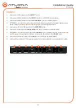
1. Connect a USB-C device to the
INPUT 1
port.
2. Connect an HDMI cable from the
INPUT 2
port to a UHD/HD source device.
3. Connect an HDMI cable from the HDMI
OUTPUT
port to a display device.
4.
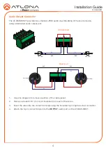
OPTIONAL: Connect an audio output device to this port using the included captive screw
block. Refer to
Audio Output Connector (page 4)
5. Connect up to two USB devices to the
USB HUB
ports.
6. Connect a computer to the
HOST USB
port, using a USB-A to USB-B cable.
7.
OPTIONAL: Connect a serial cable from
RS-232
port to a display device. Refer to
for wiring information. Connect an IR emitter to the
IR OUT
port.
8. Connect an Ethernet cable to the
LAN
port to control the AT-OME-MH21.
9.
Connect the included 5 V DC power supply from this receptacle to an available AC outlet.
Installation
4
6
7
8
9
1
2
3
5

