


7
Installation Guide
AT-HDVS-150-KIT
1. Connect up to two HD sources, using HDMI cables, to the
HDMI 1
and
HDMI 2
inputs on
the AT-HDVS-150-TX.
2. Connect a VGA cable from a VGA source to the
VGA IN
port on the AT-HDVS-150-TX.
3. Connect a 3.5 mm mini-stereo cable from the
AUDIO IN
port on the AT-HDVS-150-TX to the
analog audio source. This port allows two-channel analog audio to be included when the
VGA IN
port is selected. Refer to the User Manual for more information.
4. Connect a category cable, up to 230 feet (70 meters), from the
HDBaseT OUT
port on the
AT-HDVS-150-TX to the AT-HDVS-150-RX (or other PoE-compatible receiver). Category
cables should use EIA/TIA-568B termination.
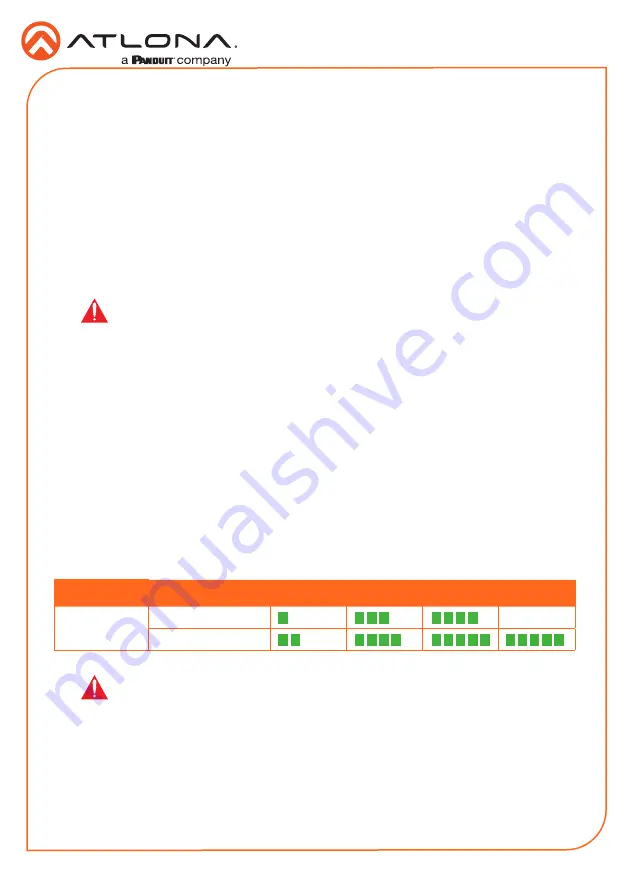
Refer to the tables below for recommended cabling when using Altona products with HDBaseT.
The green bars indicate the signal quality when using each type of cable. Higher-quality signals
are represented by more bars.
Core
Shielding
CAT5e
CAT6
CAT6a
CAT7
Solid
UTP (unshielded)
N/A
STP (shielded)
IMPORTANT:
Stranded or patch cables are not recommended due to
performance issues.
Installation
Cable Recommendation Guidelines
IMPORTANT
: Using EZ RJ-45 connectors are being used, make sure that each
twisted pair does not extend beyond the RJ-45 connector. Exposed twisted-
pair wires may cause a short when connected to the
HDBaseT OUT
port.
5. Connect an HDMI cable from the display to the
HDMI OUT
port on the AT-HDVS-150-RX.
6. Connect a category cable, up to 230 feet (70 meters), from the
HDBaseT IN
port on the unit
to the AT-HDVS-150-TX. Category cables should use EIA/TIA-568B termination.
7. Connect the included power supply to the
DC 48V
port on the AT-HDVS-150-RX.
The AT-HDVS-150-TX will be powered over the category cable, by the AT-HDVS-150-RX.


