AT-DISP-CTRL
9
HDMI IN
HDMI OUT
SOURCE
POWER
AT-DISP-CTRL
AT-DISP-CTRL
LAN
RX
PoE
TX
TX
RESET
IP MODE
RS-232 IR OUT
DC 5V
FW
HDMI IN
HDMI OUT
SOURCE
POWER
AT-DISP-CTRL
AT-DISP-CTRL
LAN
RX
PoE
TX
TX
RESET
IP MODE
RS-232 IR OUT
DC 5V
FW
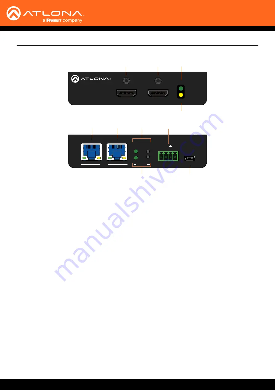
Panel Description
1
HDMI OUT
Connect an HDMI cable from this port to the display.
2
HDMI IN
Connect an HDMI cable from this port to the source
device.
3 POWER
This LED indicator glows solid green when the unit is
powered.
4 SOURCE
This LED indicator glows solid amber when a source
is connected to the
HDMI IN
port.
5
PoE LAN
Connect an Ethernet cable from a PoE-capable
network switch to the
PoE LAN
port. If a PoE switch
is not available, connect the unit to the included
power supply.
6 LAN
Connect an Ethernet cable from the LAN port to the
display device, if control will be IP-based.
7
IP MODE
Press and release this button to set the IP mode
or display the current IP address. Refer to
for more information.
8 RESET
Press and release this button to reset the unit to
factory-default settings. Refer to
for more information.
9 RS-232 / IR OUT
Connect a serial cable from the
RS-232
port, using
the included 4-pin captive screw connector, to the
display device. Connect an IR emitter from the
IR
OUT
port, using the included 4-pin captive screw
connector, and place the emitter next to the display.
10 FW
If not using PoE to power the unit, then connect
the unit to the included power supply. The same
USB to mini-USB cable can also used to update the
firmware.
1
5
6
7
2
9
4
8
10
3
Rear
Front


