

START
LOCK
Step2 Making connections
【
1
】
Connect an Ethernet cable (category 5e or better, straight) to RJ45 (female)
network cable.
IMPORTANT:
• If the procedure for the RJ45 waterproof connector (accessory) part is not correctly fol-
lowed, the waterproofing may be compromised. Do not install the camera where the RJ45
waterproof connector is exposed to constant rain or moisture.
• When you remove the RJ45 waterproof connector, be sure to follow the reverse order of the con-
necting procedures. (The RJ45 waterproof jack may be damaged when you try to remove the RJ45
waterproof connector cover with its “
⇦
” mark matching “
▶
” mark of the RJ45 waterproof jack.)
IMPORTANT:
• The 24 V AC power supply shall be insulated from the commercial AC power.
• Be sure to use the 24 V AC power supply connector kit (accessory) provided with this product.
• After processing 24 V AC connector, actually connect it to the camera and ensure it operates
normally before using it.
• Be sure to fully insert the 24 V AC power supply connector into the power cable.
Otherwise, it may damage the camera or cause malfunction.
• When installing the camera, make sure that excessive force is not applied to the power cable.
【
2
】
Assemble 24 V AC connector kit (accessory) and connect it to the power cable
of camera body as occasion demands.
①
Insert the RJ45 plug (locally procured) into
the RJ45 waterproof jack connected to
the camera.
②
Connect the RJ45 waterproof connector
cover (accessory) to the RJ45 waterproof
jack and then rotate the RJ45 waterproof
connector cover until the “
⇦
” marks align.
③
Connect the RJ45 waterproof connector cap
(accessory) to the RJ45 waterproof connector
cover and rotate the RJ45 waterproof
connector cap until there is no gap between it
and the RJ45 waterproof connector cover.
①
Recommended wire rod and array of pins of connector housing (accessory)
AWG size
(stranded wire)
#24
(0.22 mm
2
)
#22
(0.33 mm
2
)
#20
(0.52 mm
2
)
#18
(0.83 mm
2
)
Wire length
20 m
30 m
45 m
75 m
Power supply connector housing
Pin No. Signal
1
2
3
4
24 V AC LIVE (Brown)
24 V AC NEUTRAL (Blue)
Ground (Black)
Not use
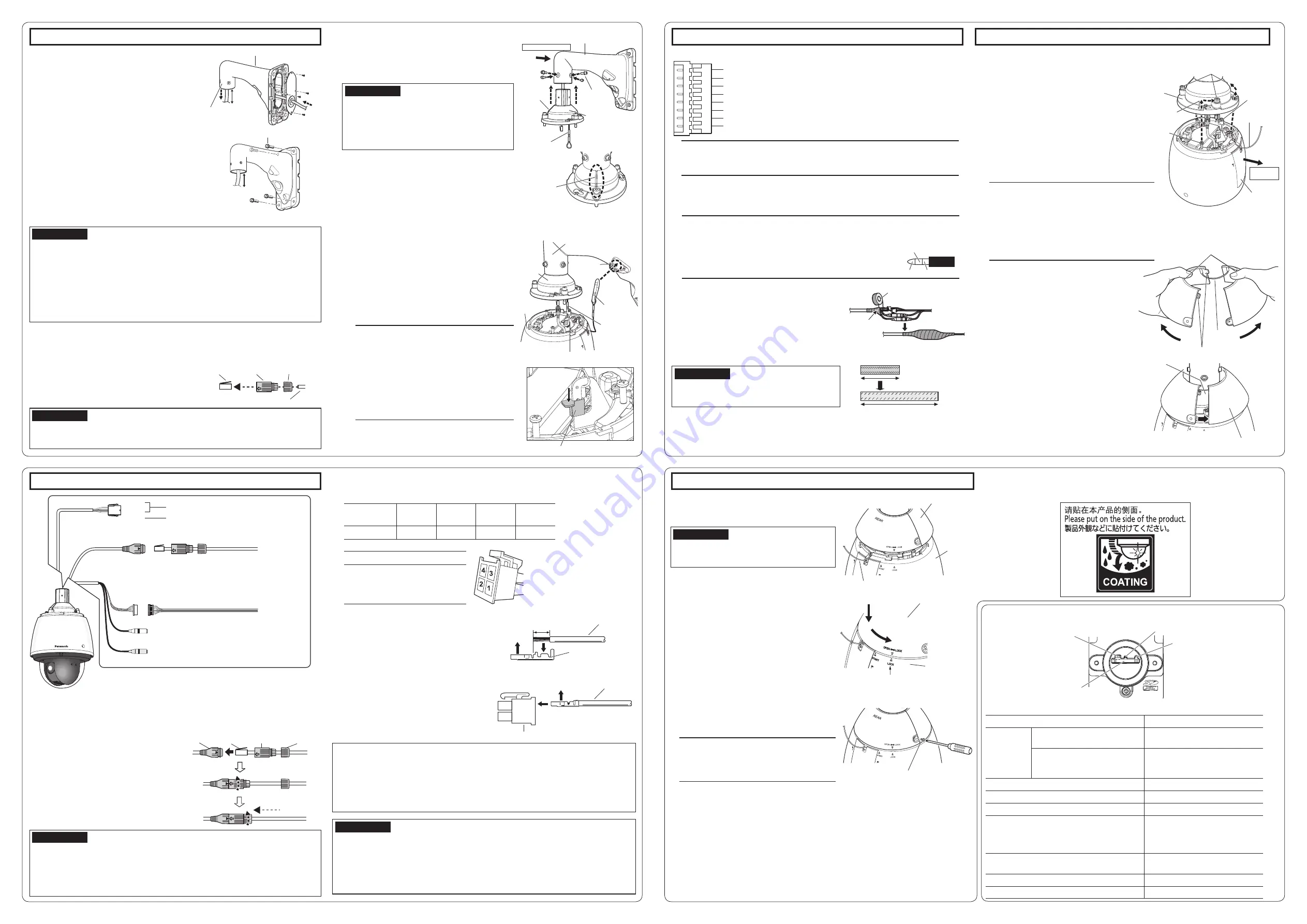
*This illustration represents WV-X6531N.
Cable
Contact (accessory)
Power supply connector housing (accessory)
Upper
A
Approx. 3 mm {1/8 inches}
Cable
Insert
Contact
(accessory)
Upper
• Remove approx. 3 mm {1/8 inches} of the
outer jacket of the cable and twist the cable
core to prevent the short circuit first.
• Insert the tip of the cable into the point A of
the contact (accessory), and hold the cable
using the cable clamp.
• Procure either of the following tools for
clamping.
Molex manual clamp tool:
57027-5000 (For UL1015),
57026-5000 (For UL1007)
• After clamping the contact and the cable,
insert the contact properly into the power
supply connector housing.
②
How to assemble the 24 V AC power supply connector kit
Step2 Making connections (continued)
Step3 Fixing the camera
【
3
】
Connect 8P alarm cable (accessory) as occasion demands.
Note:
• The default of EXT I/O terminals is “Off”. Refer to the Operating Instructions on the
provided CD-ROM for further information about the EXT I/O terminal settings.
Note:
• Special screw (fixing screw): As these are hexa-
gon screws, use a hexagon wrench (locally pro-
cured) “for M6”.
• Bend it to the inside of the cable cover to pre-
vent the installed auxiliary wire and the wiring
section from being caught in the periphery of
the cable cover.
①
Make the Panasonic logo mark on the
camera body face the front side and the
main sunshield rear cover (where SD memory
card is inserted) face the mount bracket side.
②
Insert the positioning pins on the upper part
of camera into cable cover attachment hole.
③
Rotate the camera part in a clockwise
direction when looking from the bottom and
confirm it is temporarily fixed.
④
Tighten it securely with 3 special screws
(fixing screws) of the cable cover.
Recommended tightening torque:
2.45 N·m {1.81 lbf·ft}
②
Locate the front/rear sunshields to the
position that covers the cable cover.
【
4
】
Connect a microphone or external audio line to the audio input cable as
occasion demands.
【
5
】
Connect a powered speaker to the audio output cable as occasion demands.
【
6
】
If you use a cable other than Ethernet
cable, waterproof it.
The camera body is waterproof, but the cable
ends and the inside of the mount bracket are not
waterproof. Waterproof the connection part of
each cable.
<
Waterproof treatment
>
Waterproof by using the waterproof tape
(accessory) as shown in the right-hand figure.
Note:
• The audio output can be switched to monitor output. The default is “Audio”. Refer to the
Operating Instructions on the provided CD-ROM for descriptions of how to switch the output.
• If the audio output is used for the monitor output, connect a ø3.5 mm
stereo mini connector (locally procured) to the wire as shown in the
right figure and use it.
IMPORTANT:
• Stretch the tape by approx. twice (see the illustra-
tion) and wind it around the cable. Insufficient tape
stretch causes insufficient waterproofing.
Waterproof tape (accessory)
Wind the tape in a
half-overlapping
manner
x2
Stretch the tape to approx.
twice its length.
【
1
】
Attach the camera to the cable cover (accessory).
①
Put a finger on the dent of front/rear
sunshields and unhook both sides to split it.
One side is fixed with wire to prevent loss.
【
2
】
Attach the front/rear sunshields
(accessory) to the camera.
ALARM IN1 / Black & white input / Auto time adjustment input (Black) (EXT I/O 1)
GND (Brown)
ALARM IN2 / Alarm output (Red) (EXT I/O 2)
GND (Orange)
ALARM IN3 / AUX output (Yellow) (EXT I/O 3)
GND (Light blue or green)
Unused (Blue)
Unused (Purple)
Cable cover
Front/rear sunshields
(accessory)
Dents
Unhook
Wire
Step3 Fixing the camera (continued)
③
Joint both sides of front/rear sunshields (accessory).
First, hook the wire side, and then hook the other
side.
IMPORTANT:
• Joint both sides of the front/rear sunshields
(accessory) before fitting in the main sunshield.
• Do not trap the safety wire inside.
④
Fix the front/rear sunshields on the camera
temporarily.
• Align the arrow (
▽
) with the arrow (
△
) of “START”
on the main sunshield to embed it, and then
rotate it toward arrow (
△
) of “LOCK” until it
“clicks”.
⑤
Fix the front/rear sunshields on the camera using
the front/rear sunshields fixing screw (accessory).
Recommended tightening torque:
0.72 N·m {0.53 lbf·ft}
Note:
• When removing the front/rear sunshields
(accessory), perform steps
①
~
⑤
in the
reverse order.
⑥
When the camera has been installed, remove the
protection sheet from the dome cover.
After removal, be sure not to touch the clear part of
the dome cover.
⑦
Turn on the power supply of camera and check the
screens of camera following Step 4 “Configure the
network settings” and adjust the angular field of
view. For details on adjustment of angular field of
view of camera, refer to Operating Instructions on
the provided CD-ROM.
Precautions
• Attach the “Rain wash coating caution label” carried by the camera to the surface of the camera
(Refer to the illustration below).
Front/rear sunshields (accessory)
Main sunshield
Safety wire
Front/rear sunshields fixing screw (accessory)
Front/rear sunshields (accessory)
Main sunshield
Align “
▽
” to this “
△
”
Live indicator
INITIAL SET switch
(OFF
⇔
ON)
Power indicator
Live indicator
SD memory card slot
The live indicator will light or blink as follows depending on the camera status.
Camera operation status
Live indicator status
When the
power is
turned on
Before the network connection is
established
Lights orange
→
Lights off
→
Blinks orange
→
Lights orange
When the network connection is
established
Lights orange
→
Lights off
→
Blinks orange
→
Blinks green
→
Lights green
During the standby or connection (Cable is not connected.) Lights orange
During the standby or connection (Cable is connected.) Lights green
During the upgrade process
Blinks orange
Initialization (When the network connection is
established)
Lights orange
→
Lights off
→
Blinks orange
→
Lights orange
→
Blinks orange
→
Blinks green
→
Lights green
Port forwarding error caused by the UPnP function Blinks orange (in 2 seconds intervals
(on for 1 second / off for 1 second))
Trouble happening on the camera
Blinks red
Failure in writing data on the SD memory card
Lights red
Step1 Fix the mount bracket and hang the camera (continued)
◆
Here explains an example of installation on a wall
using wall mount bracket (WV-Q122A). For detailed
installation information and procedure, refer to
operating instructions of each mount bracket.
【
3
】
Process the installation surface
Decide the attachment position and bore holes for
screws or anchors on the wall and a hole for wiring
as occasion demands.
【
4
】
Pass a cable into mount bracket and fix it
on the installation surface
①
Insert the cables coming from installation surface from rear
surface of mount bracket to internal and pull them out from
camera attachment port (cable cover attachment side).
*
When passing the cables into mount bracket, take
care not to apply unreasonable force to the cables.
②
Apply waterproof treatment to the installation sur-
face and the cap of the mount bracket backside.
③
Attach the mount bracket to wall surface using
fixing screws (4 pcs.) (M10: locally procured).
【
6
】
Attach the cable cover (accessory)
①
Fix the cable cover to WV-Q121B/WV-Q122A or
attachment pipe using hexagon screws (4 pcs.)
(M5: accessory).
Adjust the orientation of cable cover so that the
line part of cable cover faces front of the bracket.
IMPORTANT:
• “Camera mounting screw (hexagon screw (M6))”
included with WV-Q121B/WV-Q122A cannot be
used. Use the “hexagon screw (M5)” included with
the camera.
• Recommended tightening torque: 2.45 N·m
{1.81 lbf·ft}
②
Remove the tape as the installed auxiliary wire is
temporarily fixed to the inside of the cable cover
with tape.
【
7
】
Hang the camera at the installed auxiliary
wire of the cable cover and fix the safety wire
①
Move the camera to the installation location and
hitch the installed auxiliary wire of the cable cover
to the wire hook on the upper part of camera.
Next, lower the wire stopper to prevent the
installed auxiliary wire from coming off.
②
Attach the safety wire of the camera to the wire
hook section of mount bracket.
*
For the safety wire attachment position, refer to
operating instructions of each mount bracket.
IMPORTANT:
• After waterproofing the hole for fixing mount bracket, the port for pulling out the cable on
installation surface, and the cap part on rear surface of mount bracket, fix the mount
bracket on the installation surface.
• Fixing screw: Minimum pull-out strength (per 1 pc.)
WV-Q121B
1411 N {317 lbf}
WV-Q122A
823 N {185 lbf}
• Adjust the length of cable from camera attachment port of mount bracket to cable end to
150~160mm {5-29/32 inches~6-5/16 inches}. (If the cable that is pulled out is too long,
storage after wiring becomes difficult. On the contrary, if it is too short, the cable cannot
reach to the camera when installing the camera. Adjust the cable length carefully.)
◆
The following works are common to Q121B/Q122A (option) and mount bracket (locally procured).
IMPORTANT:
• Take care not to remove the rubber parts from inside the RJ45 waterproof connector cover (accessory).
• The maximum length of the Ethernet cable (locally procured) is 100 m, and the external
dimensions of it are from ø5 mm {ø3/16 inches} to ø6.5 mm {ø1/4 inches}.
【
5
】
Process the Ethernet cable (locally procured) and attach
the waterproof connector cover and cap (accessory)
First pass the Ethernet cable through the RJ45
waterproof connector cap (accessory) and then
through the RJ45 waterproof connector cover
(accessory). Next, use a specialized tool (locally
procured) to crimp the RJ45 plug (locally procured) to
the end of the Ethernet cable.
RJ45
waterproof
connector
cover
(accessory)
RJ45
waterproof
connector cap
(accessory)
RJ45 plug
(locally
pocured)
Ethernet cable (locally procured)
Line part of
cable cover
* Image seen from front surface of bracket
Wire hook on the upper part of camera
Camera
②
Safety wire
①
Installed
auxiliary wire
Wire hook
section
Mount bracket
(example: WV-Q122A)
Cable
cover
Front of the bracket
Cable cover
(accessory)
Hexagon screw
(4 pcs.)
(M5: accessory)
Mount bracket
(example: WV-Q122A)
Installed
auxiliary wire
Line part of
cable cover
Note:
• The camera is not fixed. Take care not to hit
the camera against periphery (especially the
dome cover).
• Retain a work space of 500 mm {1ft 7-11/16
inches} or more from the cable cover when
you hang the camera from it.
• The installed auxiliary wire and the safety wire
are designed assuming the only camera body
is suspended. Do not apply other loads.
Caution:
• A READILY ACCESSIBLE DISCONNECT DEVICE SHALL BE INCORPORATED TO THE
EQUIPMENT POWERED BY 24 V AC POWER SUPPLY.
• ONLY CONNECT 24 V AC CLASS 2 POWER SUPPLY (UL 1310/CSA 223) or LIMITED POWER
SOURCE (IEC/EN/UL/CSA 60950-1).
• ONLY CONNECT POWER OVER ETHERNET 54 V DC / PoE+ 54 V DC LIMITED POWER
SOURCE (IEC/EN/UL/CSA 60950-1).
Fixing screws (4 pcs.) (M10: locally procured)
150~160mm
{5-29/32 inches~
6-5/16 inches}
Mount bracket (example: WV-Q122A)
150~160mm
{5-29/32 inches~
6-5/16 inches}
Camera
attachment port
【
2
】
Power cable
【
3
】
Alarm input/output cable
【
4
】
Audio input cable (white)
To a plug-in power type microphone
【
5
】
Audio output cable (black)
To an external powered speaker
【
3
】
8P alarm cable (accessory)
To a sensor
Ethernet cable
(category 5e or better, straight)
【
1
】
RJ45 (female) Network cable
RJ45 waterproof connector (accessory)
GND
To a PoE+ hub
To the power supply
(24 V AC 50 Hz/60 Hz)
Brown
Blue
Black
Mount bracket
side
Special screw (fixing
screw) (3 pcs.)
Cable cover
(accessory)
Installed
auxiliary
wire
Safety wire
Positioning
pin (3 pcs.)
Main sunshield
rear cover
Fitting hole of
the cable cover:
3 points
Wire stopper
GND
Video output
N.C.
RJ45
waterproof
jack
RJ45
waterproof
connector
cover
(accessory)
RJ45
waterproof
connector
cap
(accessory)
RJ45 plug
(locally
pocured)


