background image

5

Basic operation

The description below explains how to operate the setup menu basically. 
The operations in the setup menu are performed with the operation buttons after calling up the setup menu on the connected video 
monitor. Refer to the installation guide for further information about the operation buttons. 
The operations in the setup menu can also be performed through the system controller (option). 
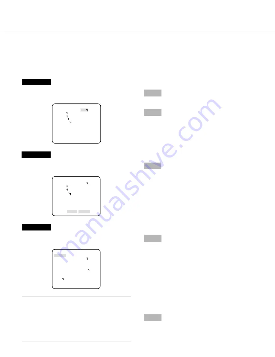
     

Screenshot 1

Hold down the setting button for more than 2 seconds simulta-
neously to call up the top screen of the setup menu. 
     

Step 1

Press the up or down button to move the cursor to "END". 

Step 2

Press  the  right  button  to  move  the  cursor  to  "SETUP",  and 
press  the  setting  button  to  change  the  setup  mode  from 
"DISABLE" to "ENABLE". 
     

Screenshot 2

The setup mode changes to "ENABLE", and the setup menu 
becomes ready to be set. 
     

Step 3

Move  the  cursor  to  the  item  to  be  set,  and  press  the  setting 
button. 
     

Screenshot 3

The selected setup screen in the setup menu appears on the 
screen. 

Note:

  •  If  the  top  screen  of  the  setup  menu  is  called  up  with  the 

operation buttons while a camera image is displayed, the 
setup  mode  is  always  "DISABLE"  to  prevent  operation 
errors. 

    To  configure  the  settings  in  the  setup  menu,  change  the 

setup mode to "ENABLE". 

  •  The cursor is a reversely highlighted part. 


Step 4

Perform the settings for each item. 

  •  Selection of setting item:

    Press the up or down button to move the cursor. 

  •  Change of settings:

    Press the right or left button. 

  •  Display of advanced setup screen:

    Press the setting button when "

O

" is attached to the tar-

get setting item. 

  •  Return to previous setup screen:

    Move the cursor to "RET" and press the setting button. 

  •  Return to the top screen:

    Move the cursor to "TOP" and press the setting button. 

Step 5

To  return  to  the  camera  image  screen,  move  the  cursor  to 
"END" and press the setting button. 
     

 MODEL   WV-CP

500

L SRS

CAMERA ID     OFF

CAMERA   

SYSTEM

SPECIAL

LANGUAGE


 END   SETUP DISABLE

 MODEL   WV-CP

500

L SRS

CAMERA ID     OFF

CAMERA   

SYSTEM

SPECIAL

LANGUAGE


 END   SETUP ENABLE

    **CAMERA SETUP** 

SCENE1

 ALC/ELC      ALC    

 SHUTTER      OFF

 AGC          ON(HIGH)

 SENS UP      OFF

 WHITE BAL    ATW

1

 DNR          HIGH

 BW MODE      OFF

 VMD

 RET TOP END

Summary of Contents for WV-CP500L

Page 1: ...ad these instructions carefully and save this manual for future use The model number is abbreviated in some descriptions in this manual Operating Instructions Color CCTV Camera Model No WV CP500L G WV...

Page 2: ...er to the installation guide for further information about how to install the camera Adobe Reader is required to read PDF When the Adobe Reader is not installed on the PC download the latest Adobe Rea...

Page 3: ...tion function setting DNR 13 8 Black and white mode setting BW MODE 13 9 VMD setting VMD 14 Perform the settings relating to the motion detection 15 Setting of scene change detection 16 Setting of det...

Page 4: ...NS UP Specifies electronic sensitivity enhancement 11 WHITE BAL Specifies white balance adjustment 12 DNR Selects the level of the digital noise reduction function 13 BW MODE Performs the setting rega...

Page 5: ...up menu appears on the screen Note If the top screen of the setup menu is called up with the operation buttons while a camera image is displayed the setup mode is always DISABLE to prevent operation e...

Page 6: ...ZOOM OFF RET TOP END BACK FOCUS SETUP ABF PUSH SW MANUAL ADJ C L B W AUTO SETUP SW LOCK OFF NEAR FAR INDICATOR XXXX RET TOP END SPECIAL SETUP CHROMA GAIN 128 AP GAIN 32 PEDESTAL 32 PIX OFF COMMUNICATI...

Page 7: ...d characters are displayed in the editing area Character entry To revise a character move the arrow in the entry range to a wrong character with use of the right or left button and enter a correct cha...

Page 8: ...ENE1 and use the right or left button to select SCENE2 The COPY SCENE1 screen will be displayed Step 3 To configure the settings of SCENE2 using the settings of SCENE1 press the setting button after m...

Page 9: ...s less visible because the camera adjusts the iris in accordance with the bright area Conversely adjusting the lens brightness for the darker areas causes the brighter areas to become washed out The S...

Page 10: ...Follow the procedure below Step 1 Move the cursor to LEVEL and use the right or left button to adjust the level When not using the SUPER D5 function Follow the procedure below Step 1 When the SUPER D...

Page 11: ...screen brighter when the illuminance of the subject becomes darker HIGH MID and LOW indicate the gain level OFF Does not increase the gain Note When SENS UP is set to the AUTO mode AGC cannot be set t...

Page 12: ...The adjustment of the color temperature ranges from approx 2 000 K to 6 000 K AWC Activates the automatic white balance control mode This adjustment is suitable for a location where a light source is...

Page 13: ...er 7 Digital noise reduction function setting DNR The digital noise reduction function reduces noise automatically under the condition of low illuminance The effect level of the noise reduction functi...

Page 14: ...a operation When the VMD function detects a motion of an object and interference in camera operation an alarm signal can be provided Refer to the following for important information about the settings...

Page 15: ...cted for detection after selection of SETUP and pressing the setting button Refer to page 16 for how to set the detection area Step4 Move the cursor to SENSITIVITY and select the detection sensitivity...

Page 16: ...ary objects are specified Up to 2 detection areas can be set Follow the procedure below Step1 Move the cursor to AREA and select SETUP and then press the setting button The AREA screen appears Step2 M...

Page 17: ...shown in white frame Step5 Use the up down right and left buttons to determine the right lower position of the area to be set and press the setting button The mark is displayed at the right of the num...

Page 18: ...he VD2 synchronization is selected either the power supply synchronization or internal synchronization can be selected Note The power supply synchronization LL setting is changeable only in the 50 Hz...

Page 19: ...ns in the camera shooting area on the screen exist those portions privacy zone are hidden Up to 8 portions can be specified for the privacy zone ON 1 Grays the zone ON 2 Mosaics the zone OFF default D...

Page 20: ...from step 3 12 Image stabilizer setting STABILIZER Whether or not to enable the image stabilizer is determined This function is effective for the case that the camera is installed on a power pole or...

Page 21: ...ted resolution will be deteriorated Step 4 Move the cursor to PUSH SW of PAN TILT and press the setting button The pan tilt setting screen appears Step 5 Use the up down right and left buttons to dete...

Page 22: ...oves in the direction the image becomes sharp er and when the level indicator moves in the direction the image becomes softer Be sure to view a monitor when the adjustment is performed Note Moire inte...

Page 23: ...gain is attached at the right side of the number when registration is completed The coordinate is expressed in figures Note To clear the registered pixel compensation point move the cursor to the numb...

Page 24: ...Does not use any receiver Default resetting CAMERA RESET The settings in the setup menu are restored to the default settings The default settings are restored by moving the cursor to PUSH SW of CAMERA...

Page 25: ...Refer to page 5 for how to call up the screen JAPANESE ENGLISH default FRAN AIS ESPA OL DEUTSCH ITALIANO To change the language to be used use the right or left button to select the target language mo...

Page 26: ...5 Camera function Gain adjustment AGC ON 1 7 6 Camera function Gain adjustment AGC OFF 1 7 7 Camera function Electronic sensitivity up SENS UP FIX ON 1 7 8 Camera function Electronic sensitivity up SE...

Page 27: ...tp panasonic net Importer s name and address to follow EU rules Panasonic Testing Centre Panasonic Marketing Europe GmbH Winsbergring 15 22525 Hamburg F R Germany Panasonic System Networks Co Ltd 2010...

Reviews: