background image

5-3

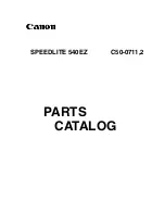
CONDUCTOR VIEW OF I/F BOARD

C24

C31

R241

C214

C215

C216

C217

R255

C220

C221

C223

C244

C2

C7

TD1

TD2

TD3

TD4

D201

D202

TD6

TD9

B2

A2

B1

A1

E1

JK1

D11

D12

D16

D17

L1

L2

TD10

TD12

TD13

TD14

TD15

TD16

TD17

TD18

TD19

TD20

TD22

TD24

TD25

TD26

TD27

TD28

TD29

TD30

TD31

TD32

TD33

TD34

TD38

Q5

TD40

TD41

TD42

TD43

TD44

TD52

VS3

VS5

L203

L204

R87

1

12

CN1

5

CN2

1

CN3

1

2

30

1

2

CN7

R96

C12

C14

SW1,3,4,

5,6

VCF284RY2A PbF

C21

C22

C23

R210

R211

R212

R216

R217

R223

R224

R225

R232

R233

C200

C201

C206

C208

R245

C209

C210

C211

C212

C213

R251

R252

R253

C218

C219

R256

C222

C224

C225

C226
C227

C228

C229

C1

C3

D1

D2

D3

D4

D5

D6

D7

D8

D200

D9

TD5

TD8

8

1

32

16

IC201

SW2

D10

D13

D14

D15

D18

L4

L5

TD11

IC1

L25

IC3

TD23

R24

TD39

Q4

R8

TD50

R45

Q200

VS1

Q201

VS2

Q202

Q203

Q204

Q205

Q206

R68

L200

L202

10

2

1

9

CN5

R97

Q250

Q251

Q252

Q253

C17

R203

R204

R205

R206

R207

R208

R209

PbF

A

A

VCF284RY2A

R28

R100

R237

R238

R246

R38

R27

R37

R23

R36

R35

R22

R34

R26

R33

R20

R21

R1

R9

R16

R86

R84

R74

R92

R247

R103

R2

R7

R227

R62

R58

R228

R94

R222

R229

R230

R215

R250

R1

10

R243

R240

R91

R89

R93

R25

R4

R5

R254

R29

R104

R75

R202

C203

R200

R201

R88

R17

C26

R3

R239

R236

R242

C245

R231

R219

R221

C207

<INDEX>

I/F BOARD
(COMPONENT
 SIDE)

Q5 OPEN

D11 OPEN
D12 OPEN
D16 OPEN
D17 OPEN
D201 A1
D202 OPEN

I/F BOARD

(COMPONENT SIDE)

1

A

B

2

3

1

A

B

2

3

<INDEX>

I/F BOARD
(PATTERN SIDE)

IC1 OPEN
IC3 A1
IC201 A2,A3

Q4 A1
Q200 A2
Q201 A2
Q202 A2
Q203 A2,B2
Q204 B2
Q205 A1,B1
Q206 A2,B1,B2
Q250 OPEN
Q251 OPEN
Q252 OPEN
Q253 OPEN

D1 OPEN
D2 OPEN
D3 B2
D4 B2
D5 B2
D6 B2
D7 OPEN
D8 OPEN
D9 OPEN
D10 A1
D13 A1
D14 OPEN
D15 OPEN
D18 OPEN
D200 OPEN

I/F BOARD

(PATTTERN SIDE)

Summary of Contents for WV-CF102E

Page 1: ...anning lines 625 lines Scanning frequency Horizontal 15 625 kHz Vertical 50 00 Hz Synchronization Internal multiplexed vertical drive VD2 Resolution Horizontal 540 TV lines at center Vertical 400 TV l...

Page 2: ...solder will tend to splash when heated too high 600 C 1112 F 8 Lead free solder Sn 3 0Ag 0 5Cu or equivalents are recommended on repairing our lead free soldered PCB Y WARNING This service informatio...

Page 3: ...asonic Corporation BE LIABLE TO ANY PARTY OR ANY PER SON EXCEPT FOR REPLACEMENT OR REASONABLE MAINTENANCE OF THE PRODUCT FOR THE CASES INCLUDING BUT NOT LIMITED TO BELOW 1 ANY DAMAGE AND LOSS INCLUDIN...

Page 4: ...CK DIAGRAM 3 2 SCHEMATIC DIAGRAM SENSOR BOARD 4 1 MAIN BOARD 1 2 4 2 MAIN BOARD 2 2 4 3 I F BOARD 4 4 POWER BOARD 4 5 CONDUCTOR VIEW SENSOR BOARD 5 1 MAIN BOARD 5 2 I F BOARD 5 3 POWER BOARD 5 4 EXPLO...

Page 5: ...ra selects black and white mode if the picture is dark or color mode if the picture is bright enough OFF Color picture is displayed normally Default setting OFF Note The simple day night function is e...

Page 6: ...ffect may not be achieved even if the mode is set to ON to detect the backlight level r Lens unit Rotate to adjust focus t Azimuth adjuster Adjusts the azimuth angle of the cam era y Tilting table Adj...

Page 7: ...arithmic Gray Scale Chart Part Number YWV2310RB99 8 Colour Chip Chart Part Number YWV2100RB98 8 White Chart or White Paper 8 EVR Electric Variable Resistor Adjustment Kit as shown in Fig 1 1 Part Numb...

Page 8: ...w Special Screw that secure the Camera Unit 8 Referring to Fig 2 5 release the hook part of the Camera Unit by using the pliers for lead or equivalent and remove the Camera Unit from the Main Unit Whe...

Page 9: ...amera Unit Fig 2 7 8 Confirm that removed the Sensor Board and the Main Board from the Camera Unit as shown in Fig 2 10 8 Referring to Fig 2 11 reconnect the connectors by using the Extension Cable Re...

Page 10: ...tments should be done with this initial setting uniess otherwise specified 8 The adjustments should be done after 10 minutes warm up 3 Connection and Setting Up for Adjustment 3 1 Connection 8 The Fig...

Page 11: ...age folder 2 Open the Install package 3 Open DISK1 file 4 Excute the SETUP EXE Store the software to the default position 5 Click OK button of iotest Setup program screen 6 Click the icon button of io...

Page 12: ...nfirm the display and click ESC button for close EEPROM CHECK menu 5 Click OPEN LOAD L button 6 Open the SOFT EV2 package and select SOFT scp_SOFT_Ver0609141435 ev2 The EV2 software will be stored in...

Page 13: ...ND Z button you can finish the EVR Adjustment 8 GRID G button is not used for adjustment 4 2 3 Adjustment Procedure 1 Click Adjust A to open adjustment menu and select Adjust 2 Select each item from t...

Page 14: ...of the Personal Computer for next adjustment 4 Pedestal Level Adjustment Test Point Video Output Connector 8 Confirm that the item 4 Pedestal Level Adjustment dis played 8 Connect the terminated Osci...

Page 15: ...t Video Output Connector 8 Confirm that the item 8 2 b Burst Level Adjustment dis played 8 Keep the Colour Temperature at 3 200 K 8 Aim the Camera at the Logarithmic Gray Scale Chart 8 Connect the ter...

Page 16: ...e 3200K B Y Matrix Adjustment Test Point Video Output Connector 8 Confirm that the item 10 2 e 3200K B Y Matrix Adjustment displayed 8 Keep the Colour Temperature at 3 200 K 8 Adjust data with ARROW...

Page 17: ...Fig 4 2 8 and Table 4 2 2 8 Press ENTER key of the Personal Computer for next adjustment 11 High Light Chroma Clip Adjustment Test Point Video Output Connector Adjust RAM 1028 8 Confirm that the item...

Page 18: ...2 50 1 49 CN2 5 1 CN2 1 5 E2 29 1 30 2 CN3 2 30 1 29 CN3 IC2 SW5 Connect by using the Extension Cable and the Extension Board Ass y for Servicing TD71 TD70 14MHz TD70 is placed in the back TO EVR ADJU...

Page 19: ...PEN OPEN OPEN OPEN OPEN OPEN OPEN C19 C46 10p C44 10p C36 1000p C2 OPEN C12 0 01 C7 OPEN C40 2200p C47 OPEN C48 OPEN C49 OPEN C13 100p C15 33p C17 100p C42 0 047 C45 560p C43 OPEN C33 10 R2 0 C30 1 R8...

Page 20: ...T7 89 DVSS7 90 DVDD7 91 I2CSCL 92 I2CSDA 93 CPUPORT0 94 CPUPORT1 95 MRESETO 96 MRESETI 97 TEST0 98 TEST1 99 REVIRQ 100 TCK 101 XSM 102 XTST 103 SMCK 104 MST 105 DVDD8 106 DVSS8 107 BSIN 108 BDBMX 109...

Page 21: ...TM2OB 33 SEG7 P70 KEY0 TM1IO 34 SEG6 P71 KEY1 TM3IO 35 SEG5 P72 KEY2 36 SEG4 P73 KEY3 37 SEG3 P74 KEY4 38 SEG2 P75 KEY5 TXD0B SBO0B 39 SEG1 P76 KEY6 RXD0B SBI0B SDA4B 40 SEG0 P77 KEY7 SBT0B SCL4B 41...

Page 22: ...D16 TD19 TD22 TD25 TD28 TD29 TD1 TD5 TD8 TD11 TD30 TD31 TD32 TD33 TD34 C244 0 1 TD50 TD38 TD39 TD52 TD40 TD41 TD43 TD44 TD14 TD23 TD20 TD17 TD26 TD42 JK1 5 2 3 1 D15 OPEN 1 2 3 D12 OPEN 1 2 3 GND E1 A...

Page 23: ...C7 4700p R7 150k R6 160k R5 12k C6 680 10 R10 0 R8 3k D3 470 L2 C10 OPEN IC2 1 VIN SW FB INV EN RT GND 8 2 7 3 6 4 5 PVIN E2 1 9V 2 5V 3 GND 4 NC 5 NC GND GND Important safety notice Components identi...

Page 24: ...1 R8 R4 R3 R34 R33 R41 C16 TD5 R59 R43 C23 TD4 R16 C5 R17 R46 TD16 R38 R22 C13 R19 R39 R23 C15 R29 R40 R24 R69 C17 TD10 TD8 TD13 TD50 TD21 TD27 TD23 TD31 TD35 TD43 TD39 TD24 TD26 TD30 TD28 TD46 TD44 T...

Page 25: ...C23 C30 R63 R42 C78 C8 C25 C47 C49 C50 C7 C40 R30 R29 R27 TP5 TP3 TP1 TP4 TP6 TP7 TP2 C48 R2 TD38 R25 R5 R3 C41 R95 R34 R1 R49 R133 R130 R43 R44 R54 R56 R62 TD15 TD39 TD19 TD27 TD31 TD33 TD41 TD37 TD4...

Page 26: ...R24 TD39 Q4 R8 TD50 R45 Q200 VS1 Q201 VS2 Q202 Q203 Q204 Q205 Q206 R68 L200 L202 10 2 1 9 CN5 R97 Q250 Q251 Q252 Q253 C17 R203 R204 R205 R206 R207 R208 R209 PbF A A VCF284RY2A R28 R100 R237 R238 R246...

Page 27: ...UCTOR VIEW OF POWER BOARD INDEX POWER BOARD COMPONENT SIDE D1 A2 POWER BOARD COMPONENT SIDE 1 A B 2 POWER BOARD 1 A B 2 INDEX POWER BOARD PATTERN SIDE IC1 A1 IC2 A2 D2 A1 B1 D3 A2 B2 POWER BOARD PATTE...

Page 28: ...6 1 MAIN UNIT 1 CAMERA UNIT Refer to page 6 3 MAIN UNIT 2 Refer to page 6 2 M1 M2 M3 M4 M5 EXPLODED VIEW 1 4...

Page 29: ...B3 PCB4 M10 M9 M6 M8 M7 E11 E12 E13 Cable Tie Serial No Label Numbers show screws and washers XTB3 8GFN XYN2 J6FN Screw Binding Head Taptite Screw Pan Head Machine Screw and Washer Ass y Description N...

Page 30: ...IT PCB1 PCB2 M18 IC2 M12 M15 M13 M14 M4 M17 M16 Numbers show screws and washers XYN2 J6FN XTB2 6GFJK Screw Pan Head Machine Screw and Washer Ass y Binding Head Taptite Black Screw Description No 2 3 E...

Page 31: ...6 4 WV CF102 M28 M29 M28 M29 M29 M27 M23 M24 M25 M21 M26 Bar Code Label PACKAGING EXPLODED VIEW 4 4...

Page 32: ...ansistor D2 B0ADCC000006 Diode TH1 D4B202400002 Thermistor 2K ohms R1 ERJ3GEY0R00 Metal 0 ohm 1 10W R2 5 ERJ2GE0R00X Metal 0 ohm 1 16W R6 ERJ3GEYJ222V Metal 2 2K ohms 1 10W R7 ERJ2GEJ100X Metal 10 ohm...

Page 33: ...IC1 C1AB00002794 Digital Signal Processor IC2 C0EBD0000066 Voltage Detector IC3 C0JBAB000624 Inverter IC4 C0ABBA000025 Operational Amplifiers IC9 C3EBGY000016 EEPROM 16k bit See Note below IC12 C0EBE...

Page 34: ...nsistor Q206 B1HBCFA00006 Transistor D3 6 B0ADCJ000015 Diode D10 B0JCME000041 Diode D13 MA2J72800L Diode D201 B0JCGD000002 Diode VS1 J0LB00000063 ZNR R3 ERJ2RKD224X Metal 220K ohms 1 16W R4 ERJ2RKD124...

Page 35: ...1DA0021 Coil 100 H L25 ELJPA100KF Coil 10 H L200 ELJFC330KF Coil 33 H L202 ELJFC100KF Coil 10 H L203 ELJPA100KF Coil 10 H L204 G1C100MA0171 Coil 10 H SW5 K0D411A00029 4 bit Dip Switch CN2 K1KA05AA0083...

Reviews: