background image

88

LOG-IN AND LOG-OUT

Before starting the following procedures, all system compo-
nents must be turned on.
The following procedures are applicable when the system
controller is connected to the unit.

■ 

Log-in

This operation is skipped when the auto log-in is set to ON.
(Refer to p. 89.)

1. Turn on the power switches of all system components. 

The OPERATE indicator will light up.

2. To turn on the power of the system controller, connect

the AC adapter to the AC outlet.
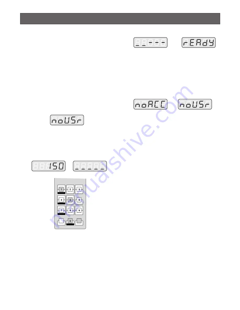
The LINK indicator lights up and "NO USER" appears
on the LED display of the system controller.

3. To select your registered operator ID number (1 to 16,

up to 2 digits), press the numeric buttons, then press
the CAM (SET) button.
The underline appears on the LED display of the con-
troller.
The factory default setting is 150.

4. To select your registered password (up to 5 digits),

press the numeric buttons, then press the CAM (SET)
button.
The factory default setting is 150.
If the operator ID and password are correct, "READY"
will appear on the LED display.

Note:

If an operator ID or password error occurs, the

PROHIBITED indicator on the controller will blink
and "NO ACC" will blink on the LED display for
about 3 seconds. Then "NO USER" appears on the
LED display. Return to step 3 and select your oper-
ator ID.

MON LOCK

DEF ON

WIPER

DEF OFF

MON (ESC)

T&D

CAM ID

MON STATUS

ALL

EVENT

ALM H

VLD H

SYS S

CAM (SET)

MULTI SCREEN SEL

SEQUENCE

AUX2 ON

AUX2 OFF

EL-ZOOM

AUX1 ON

AUX1 OFF

STILL

Note:

If the auto log-in is set to ON, any operator can login

automatically. After the controller is turned on, "AUTO"
appears on the LED display for approximately 2 sec-
onds, then "READY" automatically appears.

Summary of Contents for WJSX150 - SWITCHER - ADDENDUM

Page 1: ...rate this product please read these instructions carefully and save this manual for future use Model No WJ SX150 Matrix Switcher Operating Instructions Matrix Switcher WJ SX 150 OPERATE OPERATE LED WILL BLINK IF COOLING FAN MALFUNCTIONS ...

Page 2: ...odifications not expressly approved by the party responsible for compli ance could void the user s authority to operate this equip ment For U S A WARNING To prevent fire or electric shock hazard do not expose this appliance to rain or moisture The apparatus shall not be exposed to dripping or splashing and that no objects filled with liquids such as vases shall be placed on the apparatus CAUTION T...

Page 3: ...your outlet consult an electrician for replacement of the obsolete outlet 10 Protect the power cord from being walked on or pinched particularly at plugs convenience receptacles and the points where they exit from the apparatus 11 Only use attachments accessories specified by the manufacturer 12 Use only with the cart stand tripod bracket or table specified by the manufacturer or sold with the app...

Page 4: ...Connection with the Time lapse VCR Panasonic Models 45 Cable Specifications 46 Connection with the Time lapse VCR Non Panasonic Models 46 Connection with the PC 47 Time Adjustment with an External Equipment 47 WJ SX150 SETUP PROCEDURES 49 SETUP PROCEDURES 50 Setup Procedures 50 Description of Setup Procedures 50 WJ SX150 SETUP MENU OSD 52 Displaying SETUP MENU 52 Programming SETUP MENU 52 TIME DAT...

Page 5: ...Suspending All the Alarm Inputs 112 MULTIPLEXER OPERATIONS PS Data 113 Controlling the Unit with a PS Data System Controller 113 EXPANDED FUNCTION 115 WJ HD500 SERIES CONTROL TERMINAL MODE 116 Displaying WJ HD500 Series SETUP MENU 116 Controlling Digital Disk Recorder WJ HD500 Series 116 WJ HD100 SERIES CONTROL TERMINAL MODE 120 Displaying WJ HD100 Series SETUP MENU 120 Controlling Digital Disk Re...

Page 6: ...lapse VCR you need to install Multiplexer Board WJ SXB151 inside the matrix switcher FEATURES Multiple sequence modes 16 tour sequences and 4 group sequences Control data and timing pulse VD2 multiplexed over a coaxial cable Cable compensation selectable depending on the cable length Cameras or images on the monitors selectable with alarm sensor RS 485 cameras connectable Multiscreen display elect...

Page 7: ...abrasive detergents when cleaning the appliance body Use a dry cloth to clean the appliance when it is dirty When the dirt is hard to remove use a mild detergent and wipe gently Do not operate the appliance beyond its specified temperature humidity or power source ratings Use the appliance at temperatures within 10 C 50 C 14 F 122 F and humidity below 90 The input power source for this appliance i...

Page 8: ...9 FEATURES OF THE MATRIX SWITCHER SYSTEM ...

Page 9: ...ected to video cameras and the columns are connected to video monitors By closing a certain crosspoint switch we may connect any camera to any monitor In the example above by closing switch SW12 the camera 2 is displayed on the monitor 1 Likewise by closing SW24 camera 4 is displayed on the monitor 2 Monitoring Mode This system can control up to 16 cameras 4 monitors and 4 system controllers There...

Page 10: ...s the control data and VD2 timing pulse to the cameras On the contrary the cameras send the video signal and state signal to the unit Control data is supplied via the coaxial cable from the unit multiplexed with the camera image The unit is equipped with the circuit to multiplex or separate the video signal and control data with each channel These connections enable the control of the equipment fr...

Page 11: ...ording setting are necessary Example Operations of cameras and other connected equipment during an alarm input 1 The infrared sensor sends an alarm signal to the unit when detecting a car comes in 2 The unit enters the sequence mode associated with Monitor 1 At the same time the unit controls the digital disk recorder to change its recording mode into the alarm recording mode Monitor 1 is associat...

Page 12: ...well time 2 s Gate opens Aux 1 s s s Camera 5 Dwell time 30 s s s s Camera 1 Camera 4 Camera 5 Sensor Aux 1 Aux 2 Receiver Preset position 2 Matrix Switcher WJ SX OPERATE OPERATE LED WILL BLINK IF COOLING FAN MALFUNCTIONS Matrix switcher Alarm 3 Alarm Sequence mode Alarm mode s s Monitor 1 Monitor 2 s t t t Camera 6 s Alarm recording mode Camera 6 Preset position 1 Recorder To use WJ HD100 Series ...

Page 13: ...r Console The following are the properties which can prevent the oper ation conflict Level Setting 16 operators are classified in the level from 1 the highest to 3 the lowest A higher level operator can control more functions Password Setting Up to 5 digit numbers can be registered as a password When an operator logs in the system identifies the operator ID and password by comparing the registered...

Page 14: ...le as each step s dwell time Each step can call the desired preset position of a camera to be displayed Monitor related Functions The following functions related to monitors are configurable Monitor Selection It is necessary to select a monitor when controlling the monitor related functions such as camera images or SETUP MENU Information Displayed on the Monitors The following information is displ...

Page 15: ...e lens selection switch DC VIDEO is set to DC Focus This setting adjusts the lens focus An auto focus camera can automatically adjust the focus Zoom This setting adjusts the lens zoom rate Iris This setting adjusts the lens iris Pan Tilt Head Control Pan Tilt Camera rotates on the pan tilt heads There are two ways of control Manual control by the joystick The joystick on the system controller can ...

Page 16: ...ging to black and white pictures Camera function Shortcut function Note The specified cameras can control each function Confirm the functions of the connected cameras and external devices Changing to Black and White Pictures Color images are changeable to black and white images This function is intended for surveillance in a dark place such as an underground parking lot Camera Function Shortcut Fu...

Page 17: ...nnection etc In this case video loss history will be reserved in the sys tem and this table will display the history The loss order date time CAMERA IN number and event can be identified Up to 100 item can be reserved and they are overwritten from the oldest after more than 100 item have occurred As well as the video loss history the date of the loss and recovery the camera number and the loss sta...

Page 18: ...or backward search Forward of backward field advance Fast forward Rewind Index Refer to each device s operating instructions for details System Status Table The current system status can be identified The continuous display becomes possible by the OSD set ting MON Monitor s unit address number CAM Camera No MODE Operation mode KB Controller s unit address number OPE Operator number PRI Priority Se...

Page 19: ...camera s image in the spot mode Still display The desired image can be displayed in a still picture Live images can be displayed in multiscreen display Playback images can be displayed in spot multiscreen display STILL will appear on the active monitor Zoom The desired image on the monitor can be zoomed up to two fold Note This function is available only when a playback image is displayed in a spo...

Page 20: ... image and camera ID are recorded The camera ID can search and play back the desired camera s image The digital disk recorder WJ HD100 Series connected to the unit and time lapse VCR have the following functions The operations are conducted with their buttons or the system controller or the PC The setup of the recording device The start of the playback The stop of the playback The playback of the ...

Page 21: ...ing The administer authorization and log in log out procedure differs from the unit They are conformed to the system con troller Refer to the system controller s operating instructions Use the PS Data template supplied with the system controller as the operating procedures differ from those of the terminal mode Refer to pp 107 to 113 When connecting a recorder to the unit you may have to configure...

Page 22: ...23 DETAILED PRODUCT DESCRIPTION ...

Page 23: ... UNIT This selector is reserved for future use Normally set this switch to 1 r Mode selector MODE Selects the unit s operation mode Normally set all switches to OFF NORMAL mode as shown in the figure SX150 SOFTWARE UPLOAD Set the switches to this position when you update the firmware of the unit Refer to the operating instructions of the multiplexer board MULTIPLEXER SOFTWARE UPLOAD This mode is r...

Page 24: ...meras with the configuration in WJ SX150 Administrator Console Refer to p 81 DATA 4 can connect to the system controller via the PS Data protocol DATA HDR connects to a recorder 0 Serial port SERIAL Connects to a PC for the system configuration through WJ SX150 Administrator Console 1 RS 485 Camera port Connects to an RS 485 camera Daisy chain connection is also available 2 Line selector LINE SELE...

Page 25: ... Down L Left rewind backward field advance R Right fast forward forward field advance Available after pressing the RECORDER button while connecting to a recorder 9 Iris buttons IRIS CLOSE OPEN Close or open the lens iris of cameras equipped with the specified lens Press the CLOSE and OPEN buttons simultaneously The lens iris is reset to the factory default setting WV CU360C System Controller TERMI...

Page 26: ...n of the monitor status or research in a history table become available In combination with the SHIFT button AUX and Defroster are available In the recorder mode electronic zooming and multi screen sequence etc are available when pressed in combination with the SHIFT button 7 Monitor Escape button MON ESC MON LOCK MON Press this button to select a monitor To select a monitor press the correspondin...

Page 27: ...e time 7 Pause button PAUSE Pauses a tour sequence and the playback of the recorded images that is being run on the active moni tor Also restarts the sequence from the next step forward or the playback of the recorded images 8 Play button PLAY Starts the playback of the recorded images 9 Stop button STOP Ends a tour sequence or stops the playback of the recorded images that is being run on the act...

Page 28: ...up when the controller s power is turned on 4 Link indicator LINK Lights up when communication is established with the matrix switcher 5 Alarm indicator ALARM Lights up when an alarm condition exists 6 Monitor indicator MONITOR Lights up when the monitor number appears on the LED display 7 LED Display Displays the monitor number camera number numeric entry and error status etc 8 Camera indicator C...

Page 29: ...s this button while holding down the SHIFT button 0 Camera Set button CAM SET WIPER CAM To select a camera press the corresponding numeric button followed by this button SET To enter numeric input such as operator ID and password press this button in combination with the numeric buttons Also use this button to execute the currently high lighted selection and go into a submenu of SETUP MENU WIPER T...

Page 30: ...tor Also selects a camera If the active monitor is in spot mode press PREV while holding down the CAM SET button to replace the currently selected camera with the next lower numbered camera During the recorder mode this button moves the play back image one step forward 1 Recorder button RECORDER To enter the recorder mode press this button Note Only one operator can enter the recorder mode at one ...

Page 31: ...tem controller refer to the system controller s operating instructions Rear View DC 9V IN 3 0 9 8 7 6 5 4 3 2 1 CONTROLLER No 1 MODE 1 2 3 4 5 6 7 8 OFF ON 4 0Data ports DATA Exchange the control data with the matrix switcher via RS 485 cable supplied with the system controller 1 DC 9V Input jack DC 9V IN Use this jack to plug the AC adapter supplied with the system controller 2 Clamp Fastens the ...

Page 32: ...33 INSTALLATIONS AND SYSTEM CONNECTIONS ...

Page 33: ...trix switcher Refer to the multiplexer board s operating instructions for how to install INSTALLATIONS WARNING The installations described in the figures should be made by qualified service personnel or system installers Mounting into the Rack The matrix switcher can be mounted into the rack as described 1 Remove the four rubber feet by unwinding the four screws on the bottom of the matrix switche...

Page 34: ...order WJ HD500 Series the digital disk recorder can record all the camera channels More than one camera images can be displayed in multiscreen segments on the desired mon itor REMOTO TIMER OPERATE FULL HDD SEQUENCE SET LOCK ALARM ALARM RESET ALARM SUSPEND MULTISCREEN SELECT SET UP ESC GROUP SELECT SPOT MULTISCREEN DAYLIGHT SAVINGS EL ZOOM COPY REC PREVIEW INDEX STOP PLAY PAUSE REC FWD REV ALARM SE...

Page 35: ...se VCR Digital Disk Recorder WJ HD100A or Time Lapse VCR Camera 16 Camera 1 Camera 2 Camera 3 Max 16 Camera Inputs 16 Alarm Inputs Multiplexer Board WJ SXB151 Max 4 System Controllers 4 Monitor Outputs Available for surveillance or playback of the camera images WJ SX150 Matrix Switcher Matrix Switcher WJ SX OPERATE NEXT For Matrix Switcher WJ SX150 WV CU C 360 System Controller NEXT For Matrix Swi...

Page 36: ...r Console Connection with the Camera Sites Connect the data multiplex type cameras or camera site equipment to the CAMERA IN connectors 1 to 16 on the matrix switcher s rear panel Notes Make sure that the cable length is less than 900 m 3 000 ft between the camera site and the unit when using RG 59 U BELDEN 9259 or equivalent cables If you use locally procuring cables it is important to use only a...

Page 37: ...device s switch if required 3 Connect one end of the cable to RS 485 CAMERA and the other end to the first camera in the chain as shown in the figure Repeat this procedure for all cam eras 4 Set the termination switches of the cameras at the chain ends to ON Camera s termination switches must be set to OFF except the ones at the chain ends Notes Set the same number for the camera s unit address as...

Page 38: ...as the connected equipment The switch on a daisy chain connected unit other than the extremities must be set to OFF The switch on the end unit should be set to ON For the termination switch positions refer to the operating instruction of the corresponding unit WJ SX150 2 DATA 3 DATA 2 TERM OFF ON 4 RS485 CAMERA LINE SELECT RS485 CAMERA PS DATA DATA 4 DATA 1 DATA HDR Auto termination works inside t...

Page 39: ...Designation 14 15 16 17 18 19 20 21 22 23 24 25 Alarm Input 2 Alarm Input 4 Alarm Input 6 Alarm Input 8 Alarm Input 10 Alarm Input 12 Alarm Input 14 Alarm Input 16 GND Alarm Output 2 Alarm Output 4 GND Pin No Designation 40 Connection with the System Controllers Connect the system controller to the DATA 1 to 4 port at the unit s rear panel with the modular cable Notes Up to four system controllers...

Page 40: ... GENLOCK ON through SETUP MENU or WJ SX150 Administrator Console Refer to pp 60 or 66 WJ SX150 Matrix Switcher Monitor WJ HD500 Series Digital Disk Recorder 16 16 15 15 14 14 13 13 12 12 11 11 10 10 9 9 8 8 7 7 6 6 5 5 4 4 3 2 2 3 1 1 SIGNAL GND 10 100BASE T SPOT OUT IN EXT STORAGE COPY CONTROL ALARM VIDEO MODE DATA REMOTE WV CU50 GEN LOCK OUT SERIAL IN OUT OUT MULTISCREENOUT AUDIO CAMERA 1 1 2 2 ...

Page 41: ... are not displayed on Monitor 1 to 4 To confirm the images you need to connect another monitor with the recorder The recorder will not operate if its unit address is set to other than 1 Make sure the DATA HDR port s unit address is set to 1 through WJ SX150 Administrator Console Refer to p 66 If another number is selected you cannot control the recorder WJ SX150 Matrix Switcher WJ HD500A or a newe...

Page 42: ...nal network board WJ HDB502 is installed Select the PS Data protocol for the DATA 4 setting Refer to p 61 DATA 4 PSD PORT SELECT or p 81 Data Port If the terminal mode is selected you cannot control the recorder The recorder will not be operable if its unit address is set to 1 If the recorder s unit address in step 1 and the DATA HDR setting in step 4 are different the recorder will not be operabl...

Page 43: ...p bit 1 bit 8 Conform the parameter of 620 RECORDER UNIT ADDRESS in SETUP MENU to the setting of the recorder Refer to the recorder s operating instructions for the unit address Note After the connection configure the system through SETUP MENU and WJ SX150 Administrator Console DATA HDR Port 44 WJ HD100 series Digital Disk Recorder SIGNAL GND ALARM SERIES RECORD TIME ADJUST REMOTE MODE DATA RS 232...

Page 44: ...Notes Only Panasonic time lapse VCRs which support RS 232C are usable Refer to Cable Specifications on the next page for details of cables Both of the time lapse VCR and PC cannot be connected to the matrix switcher When configuring the system through WJ SX150 Administrator Console pull out the time lapse VCR s cable and con nect the PC s cable to the serial port To use the alarm recording functio...

Page 45: ...tion Be sure to set the VCR to automatically recover from alarm reset VIDEO IN CAMERA SW OUT GND S VIDEO AUDIO VIDEO OUT 1 2 1 2 3 4 5 6 7 8 9 10 11 12 13 14 15 16 1 2 3 4 ALARM IN COM ALARM RESET IN ALARM RECOVER OUT 5 6 7 8 ALARM OUT 1 SHOT IN TAPE END OUT 9 10 11 12 WARNING OUT HUMID OUT REC REVIEW OUT 13 14 15 16 SERIES REC IN TIME ADJUST IN TIME ADJUST OUT COM REC OUT SERIES REC OUT Time Laps...

Page 46: ...nt The specified external devices can output the time adjust ing signal to the matrix switcher This signal can adjust the time by up to 30 seconds every hour To use this function it is necessary to assign one of the alarm input terminals pin 1 to 16 to the time adjusting terminal SETUP MENU or WJ SX150 Administrator Console can assign the signal Master Clock Connection Example for Time Adjustment ...

Page 47: ...49 WJ SX150 SETUP PROCEDURES ...

Page 48: ...ry month week or day Up to 30 timer events can be registered Camera cleaning Camera cleaning can be executed on the regular time of every month week or day Daylight saving time Daylight saving times for 20 years are configurable Alarm Settings The operation parameters when an alarm is input to the unit are configurable Alarm mode The operation mode activated along with an alarm input is configurab...

Page 49: ...or control data with the camera output signals Camera title Camera title is configurable to identify the camera images on the monitor WJ SX150 Administrator Console can configure the camera title including origi nal characters Data port Usually the ports DATA 1 to 3 connect to the terminal mode system controllers RS 485 cameras will be connectable with the data port configurations through WJ SX150...

Page 50: ...C button Returns to SETUP MENU or the previous menu This operating instructions uses the symbols to describe the buttons 4 To end the setting and return to the normal view press the SETUP button while holding down the SHIFT button when SETUP MENU is displayed The system controller s SETUP indicator will go off Note The Multiplexer board version 900 MULTIPLEX ER and 1000 MUX CAMERA TITLE is display...

Page 51: ...sor to 100 TIME DATE in SETUP MENU by moving the joystick to D or C Parameters You can move the cursor to each parameter by moving the joystick to A or B Month Press the NEXT or PREV button to select the correct month Day Press the numeric buttons to enter it directly ...

Page 52: ...ROL CAM14 VIEW CONTROL CAM07 VIEW CONTROL CAM15 VIEW CONTROL CAM08 VIEW CONTROL CAM16 VIEW CONTROL 900 MULTIPLEXER VCR REC MODE 910 ALARM EXT 920 NORMAL EXT 930 DYNAMIC REC OFF 940 DUMMY BLACK OFF 950 CAM SW LOSS ON 1000 MUX CAMERA TITLE CAM TITLE CAM TITLE 1 C01 9 C09 2 C02 10 C10 3 C03 11 C11 4 C04 12 C12 5 C05 13 C13 6 C06 14 C14 7 C07 15 C15 8 C08 16 C16 420 ALARM EVENT 2 of 2 ALM MON MODE 9 1...

Page 53: ...rs Select ON or OFF by pressing the NEXT or PREV buttons ON Daylight saving time is activated OFF Daylight saving time is deactivated The factory default setting is ON After the configuration press the SETUP button while hold ing down the SHIFT button The configuration will be updat ed when closing SETUP MENU Note The start end date are configurable through WJ SX150 Administrator Console Refer to ...

Page 54: ...e NEXT or PREV button to select the desired para meters Press the numeric button s to enter a number ALARM MODE You can select an operation mode when alarm input signals are accepted by the unit Notes The alarm mode is activated when alarm input signals are assigned to the same monitor through 420 ALARM EVENT or the Alarm Event refer to p 74 window While alarm is activated you cannot operate the f...

Page 55: ... camera select TOURnn nn is a tour sequence number Executes a tour sequence when an alarm input is accepted The factory default setting is the same as the two illustra tions above Notes MODE and PRE cannot be selected by pressing the numeric buttons Press the NEXT or PREV button for selection PRE doesn t appear when TOUR 1 to 16 is selected for MODE When selecting a camera without the preset posit...

Page 56: ...r REC ONLY and press the CAM SET button The live image will be displayed Note Black image will be displayed on the monitor if the currently selected channel has no camera con nection A mark appears at the center of the monitor The following is the setting procedure 1 Move the cursor with the joystick to the desired area and then press the CAM SET key Setting point 1 is determined 2 Move the mark t...

Page 57: ...will be updated when closing SETUP MENU Notes When moving the joystick to at the bottom of CAM ERA TITLE 1 of 2 the monitor will display 2 of 2 the next page 500 CAMERA TITLE 1 of 2 CAM TITLE 1 2 3 4 5 6 7 8 500 CAMERA TITLE 2 of 2 CAM TITLE 9 10 11 12 13 14 15 16 Notes If you repeat Step 1 after setting 4 motion detection areas NG will blink at the center of the monitor for two seconds To reset a...

Page 58: ...T ADDRESS 1 With the Multiplexer board VCR Select this when a time lapse VCR is connected to the unit HD100 Select this when a WJ HD100 Series recorder is connected to the unit OFF Select this when no recorder is connected to the unit The factory default setting is OFF RECORDER UNIT ADDRESS This stands for the recorder s unit address 1 to 99 is available SYSTEM SETUP How to Display To display this...

Page 59: ...ecorder If GENLOCK OFF is selected the maximum rate recording becomes unavailable when WJ HD500A is connected to the unit CAM This stands for the camera number COMP This stands for cable compensation Select the desired setting according to the cable length S Less than 400 m 1 300 ft M 400 m 1 300 ft to 700 m 2 300 ft L 700 m 2 300 ft to 900 m 3 000 ft Refer to p 37 for available cables The factory...

Page 60: ...NTROL CAM11 VIEW CONTROL CAM04 VIEW CONTROL CAM12 VIEW CONTROL CAM05 VIEW CONTROL CAM13 VIEW CONTROL CAM06 VIEW CONTROL CAM14 VIEW CONTROL CAM07 VIEW CONTROL CAM15 VIEW CONTROL CAM08 VIEW CONTROL CAM16 VIEW CONTROL PRIORITY This stands for an operator s priority 1 to 16 is available Refer to p 14 for details on Priority Lock LEVEL This stands for an operator s restrict level It is configurable thr...

Page 61: ...connect ed to the unit The factory default setting is EXT NORMAL EXT Select this to gen lock the unit during the normal operation 002 004 to 255 field Select one of these normal recording rates if the asynchronous unit is connect ed to the unit The factory default setting is EXT DYNAMIC REC PRI Select this to give recording priority to the camera channel with the alarm input ONLY Select this to re...

Page 62: ...ck on the Add Remove Hardware button 3 Select WJ SX150 Administrator Console and click on Add Remove 4 Operate according to the direction in the window Before Using WJ SX150 Administrator Console 1 Select Start Program Panasonic WJ SX150 Administrator Console x xx or double click the WJ SX150 Administrator Console x x icon on the desktop 2 When you launch WJ SX150 Administrator Console for the fir...

Page 63: ...e description of each window for details The selection will be memorized to WJ SX150 Administrator Console while launching it Note To change the selection you have done in the Startup Menu window restart the WJ SX150 Administrator Console while holding down the SHIFT key on the PC keyboard Startup Termination 1 Select Start Program Panasonic WJ SX150 Administrator Console x xx or double click the ...

Page 64: ...ilt in multiplexer board Click on the desired radio but ton Yes Select this when the multiplexer board is installed in the unit If you select this you can configure the Multiplexer Mode window Refer to p 82 No Select this when the multiplexer board is not installed in the unit The factory default setting is No RECORDER Recorder Control Recorder window p 66 MANAGEMENT Put to SX150 Put a File to SX1...

Page 65: ...ther HD100 Recorder window or VCR 610 RECORDER CONTROL in SETUP MENU Refer to p 60 for SETUP MENU When you select HD100 or VCR make sure EXT IN is set to GENLOCK OFF Put a File to SX150 Pressing this button will start the putting of the configuration data from the PC to the unit How to Display To display this window click on the Put to SX150 button in the main window p 65 Parameters The file name ...

Page 66: ...ng camera dwell time preset position in each step Each sequence has up to 16 steps and up to 16 sequences are configurable The configuration of a tour sequence can be copied to another one the display time of a camera image the panning tilting position which has been preset in advance Notes Enter the parameters from Step 1 in a sequential order If you skip a step it will result in an error After s...

Page 67: ...n and closes the Group Sequence window Cancel Exit button Cancels the configuration and closes the Group Sequence window Note The tour sequences with different total step number and dwell time are not configurable in a group sequence DELETE button Deletes the configuration of all the steps of the selected tour sequence COPY button Copies the configuration of all the steps of the selected tour sequ...

Page 68: ...week Monthly To execute the event at a desired time and day s of the month check on this box To determine the time click on the Hour and Minute boxes Action Group Check on the desired action to execute Tour Sequence Configures and executes the tour sequence according to the schedule in the Scheduled Mode group When you have selected Tour Sequence select the number of monitor Mon 1 to 4 and tour To...

Page 69: ...ates when the day light saving time starts and ends Camera Cleaning This window configures the parameters of camera cleaning function the schedule daily weekly or monthly and cam eras to be cleaned How to Display To display this window click on the Camera Cleaning button in the main window p 65 Parameters Camera Auto Cleaning Checking on the box will enable the configuration Schedule Mode Group Ch...

Page 70: ...spot mode or tour sequence Even more than one alarm are input the image associat ed to the initial alarm is continuously displayed Notes The alarm mode is activated when alarm input signals are assigned to the same monitor through 420 ALARM EVENT or the Alarm Event refer to p 56 or p 74 win dow While alarm is activated you cannot operate the func tions related to the multiplexer board Alarm Input ...

Page 71: ...rations from system controllers when REC ONLY is selected OFF An alarm input is not accepted via the SERIAL port The factory default setting is ON MUX MOTION DET ON This stands for that the unit s motion detector is activated When a camera detects the brightness level change and transmit an alarm signal the alarm associated sequence spot image is displayed on a monitor and alarm record ing will st...

Page 72: ...ber in Spot Tour Position 1 to 64 is selec table for Pre When the camera is not equipped with the preset position function select Notes If having selected a tour sequence for a monitor anoth er tour number or spot camera will not be available when selecting the monitor for another alarm event That will result in an error In the factory default setting Tour 1 to 4 is selectable To select Tour 5 to ...

Page 73: ...This group configures each operator s password level and priority ID Enter an operator s ID From 1 to 99999 are avail able Password Enter a password From 1 to 99999 are available Level Select 1 2 or 3 Priority Select the operator s priority from 1 highest to 16 lowest Camera Access Group This group configures the camera operation coverage of each operator Click on each camera s checkboxes and dete...

Page 74: ... Activating a tour or group sequence Program Preset Position Registering a camera s pre set position OSD Control Displaying SETUP MENU Camera Control Controlling a camera Recorder Control Controlling the recorder Recorder Setup Displaying the recorder s setup menu Save Exit button Saves the configuration and closes the Level Table window EXIT button Cancels the configuration and closes the Level T...

Page 75: ...g out is not assignable Refer to p 81 for details on data port setting When PSD is set for DATA 4 in the Data Port refer to p 81 window its port number is displayed in gray and auto log in log out is not assignable The factory default setting of the DATA 4 is PSD Time Date This window configures the unit s clock display pattern The unit s clock time is also adjustable This picture is the example f...

Page 76: ...e setup file update will be necessary Refer to p 67 Put a File to SX150 Cable Compensation VD2 DATA This window configures the following parameters of each camera the cable length for transmission loss compensa tion and whether to send the VD2 timing pulse or control data with the camera output signals How to Display To display this window click on the Cable Compensation VD2 button in the main win...

Page 77: ...am era title The cursor blinks at the first block in the text box Note When the desired camera s tab does not appear click on the buttons A or B beside the tabs 2 Click on the or button to move the cursor to the desired position 3 Click on the desired character button in the Fixed Font or User Font box The character will be entered in the text box 4 Repeat steps 2 and 3 to enter the camera title 5...

Page 78: ...cter 1 Click on the desired characters in the User Font box When making a new character click on a blank The selected user font character are displayed here in 12 x 13 dots 2 Click on or to make a character and will appear alternately by clicking will change into black after the character is regis tered in the User Font box 3 When finishing the edit click on the Save button The edited character wi...

Page 79: ...able RS485 Camera Daisy RS 485 Camera Daisy Select the number s of the camera s connected to the RS 485 daisy chain Data 1 to 3 are connectable to either of cameras and system controllers When connecting cameras to these ports select the connected camera number s PS Data mode This stands for the PS Data parameters of the DATA 4 port Logout Time Select the desired operable time before logout OFF 10...

Page 80: ...ecret view OFF Secret view function is unavailable The factory default setting is OFF Sequence Mode Select the sequence type by clicking on the radio button Quad Multiplexer sequence is activated The monitor display will be changed as 4A 4B 4C 4D 3 1 Images are displayed in 4 multiscreens and the images of Camera 4 to 16 are displayed in the sequence mode at the right bottom of the monitor The ima...

Page 81: ...ault setting is OFF System Group Camera SW Loss Select the desired setting by click ing on the drop down menu ON CAM SW LOSS will blink on the associated moni tor when loss of the camera switching pulse is detected OFF CAM SW LOSS will not appear on the monitor The factory default setting is ON Dummy Black Select the desired setting by clicking on the drop down menu ON The black image will be disp...

Page 82: ...it a user font character Save Exit button Saves the configuration and closes the Multiplexer Board Camera Title window Cancel Exit button Cancels the configuration and closes the Multiplexer Board Camera Title window Select Setup Data File The setup file is selectable by pressing this button For example this function will be used when making a new setup file with the factory default setting or con...

Page 83: ...ete the operator selected in the Accounts group click on this button Save Exit button Saves the configuration and closes the Account Manager window Cancel Exit button Cancels the configuration and closes the Account Manager window Edit Account Manager Add a Registration Operator 1 Click on the button 2 Enter the name in the Name box and the password in the Password box Name Up to 20 alphanumeric c...

Page 84: ...munication port for the con nection to the unit Baud Rate Select the desired baud rate communica tion speed 4800 9600 19200 or 38400 bps is selectable The factory default setting is 38400 bps Fixed Parameter Group The data bit 8 bit parity none and stop bit 1 bit are displayed Note These parameters are fixed Save Exit button Saves the configuration and closes the Communication Port window Cancel E...

Page 85: ...87 OPERATING PROCEDURES TERMINAL MODE ...

Page 86: ...D display of the con troller The factory default setting is 150 4 To select your registered password up to 5 digits press the numeric buttons then press the CAM SET button The factory default setting is 150 If the operator ID and password are correct READY will appear on the LED display Note If an operator ID or password error occurs the PROHIBITED indicator on the controller will blink and NO ACC...

Page 87: ...er to p 77 Auto Login Logout SHIFT CALL PRESET PROGRAM PRESET PAUSE TOUR SEQ NEXT AUTO PAN PAUSE CAM FUNC CLEAR LOG OUT MON LOCK DEF ON WIPER DEF OFF MON ESC T D CAM ID MON STATUS ALL EVENT ALM H VLD H SYS S CAM SET MULTISCREENSEL SEQUENCE AUX2 ON AUX2 OFF EL ZOOM AUX1 ON AUX1 OFF STILL Auto Log in If the auto log in is set to ON any operator can login auto matically After the controller is turned...

Page 88: ...itor number returns to the normal display on the active monitor After the log in procedure the following operations are available to control the system The operation begins with selecting a monitor then the selected camera appears the active monitor Monitor Selection 1 To select the desired monitor number 1 to 4 press the numeric button 2 Press the MON ESC button to execute the selection The MONIT...

Page 89: ...RECORDER INDEX STOP PLAY PAUSE Note If you select a wrong number press the CLEAR button to clear the input 4 If the selected camera number is not valid the PRO HIBITED indicator and the number on the LED display will blink for about 3 seconds Return to step 2 and select a new camera number 5 To replace the currently selected camera with the next higher numbered camera press the NEXT button 6 To re...

Page 90: ... set the lens focus automatically 3 Press the ZOOM WIDE TELE buttons while watching the monitor The lens iris is adjusted to obtain the desired image Press the TELE button to bring an object optically clos er Press the WIDE button to widen the scene optically Moving the zoom wheel controller of WV CU360CJ can also adjust the lens zoom 4 Press the IRIS CLOSE OPEN buttons to close open the lens iris...

Page 91: ...ic input 4 Press the CALL PRESET button while holding down the SHIFT button to save a preset position of the selected camera SHIFT CALL PRESET PROGRAM PRESET PAUSE TOUR SEQ NEXT AUTO PAN PAUSE CAM FUNC CLEAR LOG OUT MON LOCK DEF ON WIPER DEF OFF MON ESC T D CAM ID MON STATUS ALL EVENT ALM H VLD H SYS S CAM SET MULTISCREENSEL SEQUENCE AUX2 ON AUX2 OFF EL ZOOM AUX1 ON AUX1 OFF STILL Notes If the ent...

Page 92: ...ctions to the defaults Notes Refer to the operating instructions of the selected camera for details Move the joystick while holding down the SHIFT button to move the camera smoothly for presetting the positions in the camera s SETUP MENU 8 To close the camera s SETUP MENU press the F1 but ton while holding down the SHIFT button The CAM SETUP indicator goes off CAMERA FUNCTION CONTROL SETUP SHIFT R...

Page 93: ...ON ESC button to exit from the mode Note When the black and white parameter is set to AUTO in the camera s SETUP MENU this function is disabled SETUP SHIFT REW FF STEP CALL PRESET PROGRAM PRESET GROUP SEQ PAUSE SUSPEND F1 CAM SETUP ALL RESET ACK RESET F2 TOUR SEQ PREV NEXT STOP OSD AUTO PAN RECORDER INDEX STOP PLAY PAUSE CAM FUNC CLEAR LOG OUT MON LOCK DEF ON WIPER DEF OFF MON ESC T D CAM ID MON S...

Page 94: ...P SHIFT REW FF STEP CALL PRESET PROGRAM PRESET GROUP SEQ PAUSE SUSPEND F1 CAM SETUP ALL RESET ACK RESET F2 TOUR SEQ PREV NEXT STOP OSD AUTO PAN RECORDER INDEX STOP PLAY PAUSE CAM FUNC CLEAR LOG OUT MON LOCK DEF ON WIPER DEF OFF MON ESC T D CAM ID MON STATUS ALL EVENT ALM H VLD H SYS S CAM SET MULTISCREENSEL SEQUENCE AUX2 ON AUX2 OFF EL ZOOM AUX1 ON AUX1 OFF STILL 3 Press the assigned numeric butto...

Page 95: ...while holding down the SHIFT button to turn on the user s auxiliary switch 1 of the receiver Press the button 2 while holding down the SHIFT but ton to turn off the user s auxiliary switch 1 of the receiv er 3 Press the button 6 while holding down the SHIFT button to turn on the user s auxiliary switch 2 of the receiver Press the button 5 while holding down the SHIFT button to turn off the user s ...

Page 96: ... the PAUSE NEXT or PREV button to operate the group sequence Refer to steps 5 to 8 of Tour Sequence in this page for how to use these buttons 5 To stop the sequence select one of the monitors that are being run on the selected group sequence then press the STOP button RUNNING SEQUENCE SETUP SHIFT REW FF STEP CALL PRESET PROGRAM PRESET GROUP SEQ PAUSE SUSPEND F1 CAM SETUP ALL RESET ACK RESET F2 TOU...

Page 97: ...tor On screen Display OSD Position Control The procedure described below lets you determine the dis play positions such as camera title clock and status on the active monitor screen Moving the Clock Display Move the joystick while holding down the OSD SHIFT and 1 buttons 1 will move to the desired direction Moving the Camera Title Display Move the joystick while holding down the OSD SHIFT and 2 bu...

Page 98: ...IFT and 5 buttons 1 2 3 and 4 will move to the desired direction System Status Table The table shows the current system status 1 Select the desired monitor Refer to p 90 Monitor Selection 2 Press the button 9 while holding down the OSD button OSD will appear on the LED display and the SYSTEM STATUS table will appear on the active monitor as shown in the figure The columns in the table indicate the...

Page 99: ...YY MM DD HH MM SS ALARM EVENT 016 2001 08 21 18 59 08 03 ALARM 015 2001 08 21 18 58 08 03 ACK 014 2001 08 21 18 57 08 03 RESET 013 2001 08 21 18 55 08 07 ALARM 012 2001 08 21 18 54 08 07 ACK 011 2001 08 21 18 53 08 07 RESET 010 2001 08 21 18 53 00 09 ALARM 009 2001 08 21 18 52 08 09 RESET 008 2001 08 21 18 51 08 06 ALARM 007 2001 08 21 18 50 08 06 ACK SETUP SHIFT REW FF STEP CALL PRESET PROGRAM PR...

Page 100: ...eo output signals are sent to Monitor 1 For example when the alarm sensor con nected to the alarm input 1 becomes active the camera input connector 1 s image appears on Monitor 1 ALARMnn appears on the monitor The display indicates the image is input through the alarm nn nn is the alarm number When more than one alarm signal input has been accepted ALARMnn appears on the monitor Alarm output signa...

Page 101: ... inputs Alarm Reset 1 Select a monitor which displays ALARM 2 When more than one alarm signal has been input the second earliest alarm image appears on the monitor after the current alarm image is reset 3 To reset all the alarms repeat steps 1 and 2 The moni tor the LED display and the indicator will change as fol lows ALARMnn will disappear from the monitor The LED display will return to the stat...

Page 102: ...CAM SET button Still Playback Spot Picture The spot picture is changed into the still picture 1 Select the desired monitor and camera number Refer to p 90 Monitor Selection and Camera Selection The monitor number and camera number will appear on the LED display 2 Press the RECORDER button Refer to p 116 Recorder Mode The system will enter the recording mode 3 Press the PLAY button Refer to p 117 N...

Page 103: ...l by pressing a numeric button and then pressing the CAM SET button The selected camera image will be displayed in a playback spot pic ture 5 Press the button 4 while holding down the SHIFT but ton sings will appear on the image 6 To move the signs within the picture move the joy stick 7 Press the button 4 while holding down the SHIFT but ton The area surrounded by the signs will be zoomed up 8 To...

Page 104: ...107 OPERATING PROCEDURES PS DATA ...

Page 105: ...o log in function of the unit To use this function use a terminal mode system controller You cannot use the auto log out function of the unit You cannot move the clock camera title event and or monitor status display with a PS Data controller Use a terminal mode system controller Operators using the PS Data system controller have the highest priority to all those using the terminal mode system con...

Page 106: ...ected monitor will be activated Priority Lock You can apply or release priority lock by entering the func tion code Monitor display is the same as those of terminal mode Refer to p xx for the illustrations 1 Select the desired monitor Refer to Monitor Selection 2 Press the SHIFT button and enter 101 by pressing the numeric buttons 3 Press the FUNCTION button The function will be exe cuted If the p...

Page 107: ...era refer to the system controller s operat ing instructions to stop the sequence The monitor will return to the spot mode Group Sequence The following function is available only if a group sequence has been previously established in WJ SX150 Administrator Console The group sequence has ID numbers Group 1 is 17 Group 2 is 18 Group 3 is 19 and Group 4 is 20 As described earlier a group sequence det...

Page 108: ...eps 1 and 2 above OSD will appear on the LED display and the ALARM HISTORY table will appear on the active monitor You cannot control OSD display position MONITOR DISPLAY CONTROL Function Code Controller Status Note Displaying the clock 104 Pressing again will hide the display Displaying the camera title 105 Pressing again will hide the display Displaying the event 106 Pressing again will hide the...

Page 109: ...umbered camera input connectors All the video output signals are sent to Monitor 1 For example when the alarm sensor con nected to the alarm input 1 becomes active the camera input connector 1 s image appears on Monitor 1 ALARMnn appears on the monitor The display indicates the image is input through the alarm nn nn is the alarm number When more than one alarm signal input has been accepted ALARMn...

Page 110: ...troller s operating instructions are not mentioned here Refer to them Controlling the Unit with a PS Data System Controller 1 Before operating the recorder it is necessary to enter the recorder mode Refer to p 124 or p 125 2 Enter the desired function code refer to the diagram and press the FUNCTION button MULTIPLEXER OPERATIONS PS Data ...

Page 111: ...115 EXPANDED FUNCTION ...

Page 112: ...stick to UP Moves the cursor up Joystick to DOWN Moves the cursor down Joystick to L t Moves the cursor to the left Joystick to R s Moves the cursor to the right CAM SET button Executes the selections and dis plays a submenu NEXT button Increments a parameter PREV button Decrements a parameter MON ESC button Returns to SETUP MENU or the previous menu 5 To end the setting and return to the normal v...

Page 113: ...the playback press the PLAY button The sys tem will enter the playback mode Then the most recent recorded image will be played back To pause the playback press the PAUSE button To stop the playback press the STOP button To resume the playback press the PLAY button To move forward backward search during the play back move the joystick rightward leftward or press REW FF button Joystick to R B FF Sea...

Page 114: ...humbnail Display NEXT button Increments a parameter PREV button Decrements a parameter PLAY button Starts the playback of a record pointed by the cursor Note The PLAY button is deactivated in the search editing area Electronic Zooming EL ZOOM Playback images can be electrically zoomed besides a camera s optical zooming 1 Enter the recorder mode Refer to p 116 Recorder Mode 2 Press the PLAY button ...

Page 115: ...een display Other Operations SHIFT ZOOM WIDE buttons Selects a group to be SHIFT ZOOM TELE buttons Changes the display mode of the Record List between the alarm search ON and OFF ON Displays only the Alarm and Emergency Record List of the selected group OFF Displays all the record lists for the selected group SHIFT REW FF STEP GROUP SEQ PAUSE TOUR SEQ PREV NEXT OSD PLAY PAUSE MON LOCK DEF ON WIPER...

Page 116: ...d into 4 9 or 16 multiscreen segments to display camera images 1 Select the desired monitor and camera Refer to p 90 Monitor Selection and p 91 Camera Selection The monitor number and camera number will appear on the LED display 2 Press the RECORDER button on the system controller The system will enter the recorder mode and the RECORDER indicator beside the button will light up 2 To start the play...

Page 117: ...wn in step 2 The cursor can be adjusted by moving the joystick rightward or leftward 2 Press the PLAY button After the search through the date and time the recorded image will be played 3 To return to the multiscreen display press the STOP button ALARM RECALL 1 OF 10 NO DATE TIME ALM 99 JUN 9 00 00 00 00 T 98 JUN 1 00 02 34 56 T 97 JUN 1 00 01 10 01 V 96 MAY31 00 23 34 45 V 95 MAY30 00 02 00 20 T ...

Page 118: ...ecording Normal Playback The operations are the same as WJ HD500 Series Refer to p xx Normal Playback Fast forward 1 Press the FF button to fast forward the tape during the stop 2 To stop fast forwarding press the STOP button Note Pressing the FF button during fast forward will start playback Rewind 1 During the stop press the REW button to rewind the tape 2 Press the STOP button to stop rewinding...

Page 119: ...se VCR To Operate the Multiscreen Display The operations are the same as WJ HD500 Series Refer to p 117 Multiscreen Segment Switching Manual Recording Refer to the time lapse VCR s operating instructions for how to operate Normal Playback 1 Enter the recorder mode Refer to p 116 Recorder Mode 2 Do the playback procedure using the buttons on the front panel Refer to the time lapse VCR s operating i...

Page 120: ...enter the recorder mode 4 Enter the desired function code and then press the FUNCTION button Refer to the diagram 5 To select a camera channel press the numeric button s then CAM button The system will exit from the recorder mode and the selected camera image will be displayed on the monitor Notes Only one operator can enter the recording mode The images from the recorder which are displayed on th...

Page 121: ...and you will enter the recorder mode 4 Enter the desired function code and then press the FUNCTION button Refer to the diagram 5 To select a camera channel press the numeric button s then CAM button The system will exit from the recorder mode and the selected camera image will be displayed on the monitor Notes Only one operator can enter the recording mode The images from the recorder which are di...

Page 122: ... the system through WJ SX150 Administrator Console OSD SETUP MENU and time lapse VCR s SETUP MENU Refer to p 34 Installing the Multiplexer Board p 45 Connection with the Time lapse VCR Panasonic Models p 52 WJ SX150 SETUP MENU OSD and p 64 WJ SX150 ADMINISTRATOR CONSOLE The time lapse VCR s SETUP MENU cannot be displayed from a system controller Controlling the Time lapse VCR with a PS Data System...

Page 123: ...ing the OSD button LOSS CH nn will disappear from the monitor Camera Switching Pulse Loss Display When loss of the camera switching pulse is detected SW LOSS will blink on the monitor When the camera switching pulse is recovered SW LOSS will disappear from the monitor LOSS CH01 LOSS CH01 MON LOCK DEF ON WIPER DEF OFF MON ESC T D CAM ID MON STATUS ALL EVENT ALM H VLD H SYS S CAM SET MULTISCREENSEL ...

Page 124: ...r the data port If 485 CAM is selected for the port the log in will be invalid Your ID user number or password may be wrong Refer to your Operator Registration worksheet Or open the Operator Regis tration window refer to p 75 and reconfigure your ID user number and password Monitor is not selectable The monitor selection setting may be wrong Open the Monitor Selection window refer to p 76 and conf...

Page 125: ...he setting When the BUSY indicator is lighting on the system controller a higher priority operator has selected the camera Select another camera Wait until a higher priority operator fin ishes controlling the camera While the PROHIBITED indicator is lighting on the system controller you are prohibited to control the camera Open the Operator Registration window refer to p 75 and reconfigure the set...

Page 126: ...the setting if necessary Refer to p 76 You are not authorized to reset an alarm Confirm the Level Table window in WJ SX150 Administrator Console and reconfigure the setting if necessary Refer to p 76 While the PROHIBITED indicator is lighting on the system controller you are prohibited to control the monitor Open the Level Table refer to p 76 or Monitor Selection window refer to p 76 and reconfigu...

Page 127: ...131 APPENDIX ...

Page 128: ...communication speed to that of the unit The unit s communication speed is configurable by changing COM SPEED in SETUP MENU Data parity and stop bits have been set as follows Item Parameter Data length 8bit fixed Parity bit NONE fixed Stop bit 1bit fixed Hardware flow control ER DR RS CS Not supported yet Software flow control Xon Xoff Not supported yet Wait Time Not supported yet 1 Transmission Co...

Page 129: ...SE ANS HmmSO mm Monitor No CMD HmmSI ANS HmmSI mm Monitor No Available only during sequence pause CMD HmmSD ANS HmmSD mm Monitor No Available only during sequence pause Priority lock CMD HmmPR ANS HmmPRn CMD HmmSO Basic Operation Transmission Command ASCII OSD display ON OFF or Moving OSD display posi tion CMD Hmmss o ANS HmmALn Transmission command toggles OSD display ON or OFF Use o parameter wh...

Page 130: ...rd CMD AmmJL mm Monitor No Setup Control Move the cursor rightward CMD AmmJR mm Monitor No Move the cursor upward CMD AmmJU mm Monitor No Move the cursor downward CMD AmmJD mm Monitor No Enter 0 Enter 1 CMD AmmT0 CMD AmmT1 mm Monitor No mm Monitor No Enter 2 CMD AmmT2 mm Monitor No Enter 3 CMD AmmT3 mm Monitor No Enter 4 CMD AmmT4 mm Monitor No Enter 5 CMD AmmT5 mm Monitor No Enter 6 CMD AmmT6 mm ...

Page 131: ... panning Max is C0 and min is 81 Tilting speed yy 00 STOP yy 01 to 40 HEX direction tilting Max is 40 and min is 01 yy 81 to C0 HEX direction tilting Max is C0 and min is 81 Camera Control CMD CmmZMccn Zoom mm Monitor No cc Camera No n 0 STOP n 1 TELE n 2 WIDE Focus CMD CmmFCccn mm Monitor No cc Camera No n 0 STOP 1 NEAR 2 FAR 3 AUTO FOCUS Iris CMD CmmIRccn mm Monitor No cc Camera No n 0 STOP n 1 ...

Page 132: ... Move the cursor leftward CMD AmmJR Move the cursor rightward CMD AmmJU Move the cursor upward CMD AmmJD Move the cursor downward CMD AmmST SET CMD AmmES ESC CMD AmmIN RESET CMD AmmDE ALL RESET Program Preset Position CMD CmmPSccnn mm Monitor No cc Camera No nn 01 to 64 Preset position No Call Preset Position CMD CmmPMccnn mm Monitor No cc Camera No nn 01 to 64 Preset position No nn 00 Home positi...

Page 133: ...ANS RmmPL mm Monitor No Pause CMD RmmPA ANS RmmPA mm Monitor No Stop CMD RmmSPn ANS RmmSPn mm Monitor No n 0 Stop playback n 1 Stop recording Recorder button CMD HmmRS ANS HmmRS Playback images of HD500 Series appear on the monitor Recorder mode To cancel the recorder mode enter the STOP command then Camera Selection command Refer to p 107 Live Playback image CMD RmmVS ANS RmmVSn Necessary when us...

Page 134: ...ting area CMD RmmTMn ANS RmmTMn Available only for Record List and Thumbnail Display of WJ HD500 Series Transmission command toggles search edit ing area ON OFF or starts search mm Monitor No n 0 OFF n 1 ON n 2 Search start mm Monitor No Transmission command changes the monitor display between index and live image Setup control commands refer to p 134 are available while the index is displayed Gro...

Page 135: ...YMMDDhhmmss cc ee s YYYY Year MM Month DD Day hh Hour mm Month ss Second cc Alarm number associated with the cam era number 00 when the alarm is suspended ee Event 00 ALARM 01 ACK 02 RESET s Daylight saving time summer time 0 OFF 1 ON nnn video loss total number 000 to 100 Event of video loss n n is a number Display pattern YYYYMMDDhhmmss cc ee s YYYY Year MM Month DD Day hh Hour mm Month ss Secon...

Page 136: ... a yyyymmdd hhmm ss b a Event 0 ALARM 1 ACK 2 RESET yyyy Year mm Month dd Day hh Hour ss Second b Daylight saving time summer time 0 OFF 1 ON Item Transmission Command ASCII Response ASCII Parameter ASCII Miscellaneous Control ...

Page 137: ...r digit and range are valid but the operation mode is invalid ER303 Gateway reception overflow Reception buffer overflow has occurred on the other device during the gateway communication ER305 Gateway timeout error Timeout error has occurred during the gateway communication ER309 Internal error The internal processing error has happened Example The command is valid but it cannot be executed 1 The ...

Page 138: ... is the same as that of WJ SX150 Administrator Console For example the Operator Registration worksheet supports the Operator Registration window The worksheets rows columns and fields are arranged to match WJ SX150 Administrator Console configuration require ments 1 Reproduce the worksheets You may need dozens of copies 2 Reproduce instructions for the configuration windows You can attach the port...

Page 139: ...order Tour Sequence Step 1 2 3 4 Camera Preset position Dwell time Remark Tour __ 16 5 6 7 8 9 10 11 12 13 14 15 16 Step 1 2 3 4 Camera Preset position Dwell time Remark Tour __ 16 5 6 7 8 9 10 11 12 13 14 15 16 Built in multiplexer board Recorder Control Unit Address EXT IN Yes No OFF HD100 HD200 HD500 VCR Genlock off on ...

Page 140: ...144 Group Sequence Step 1 2 3 4 Camera Preset position Dwell time Remark Tour __ 16 5 6 7 8 9 10 11 12 13 14 15 16 Group 1 2 3 4 Monitor 1 Monitor 2 Monitor 3 Monitor 4 ...

Page 141: ...on Every Schdule Mode Weekly Monitor Camera Action Camera Auto Cleaning Daylight Saving Time Daily Every Hour Minute Sunday Monday Tuesday Wednesday Thursday Friday Saturday Monthly Every Day Cam 1 Cam 9 Cam 13 Cam 2 Cam 10 Cam 14 Cam 3 Cam 11 Cam 15 Cam 4 Cam 12 Cam 16 Schdule Mode Weekly Cam 5 Auto Cleaning Camera Cam 8 Cam 6 Cam 7 Every Start End Start End ...

Page 142: ...N O N C Time 6 N O N C Time 7 N O N C Time 8 N O N C Time 9 N O N C Time 10 N O N C Time 11 N O N C Time 12 N O N C Time 13 N O N C Time 14 N O N C Time 15 N O N C Time 16 N O N C Time Alarm Mode Alarm Mode Dwell Alarm Input Camera Site Alarm OFF ON REC only OFF ON REC only OFF ON REC only OFF ON REC only Sequence Mode sec sec Alarm Port Serial Port Mux Motion Det OFF Hold Mode Auto Reset Time ...

Page 143: ...Setup Alarm History Display Video Loss History Display System Status Display Single Alarm Reset All Alarm Reset Alarm Suspend Camera View Call Sequence Program Preset Position Camera Control Recorder Control Recorder Setup OSD Control Monitor Selection Monitor 1 Monitor 2 Monitor 3 Monitor 4 Controller 1 KB1 Controller 2 KB2 Controller 3 KB3 Controller 4 KB4 OK NG OK NG OK NG OK NG OK NG OK NG OK ...

Page 144: ... Auto Log out Camera Cable Compensation VD2 DATA Cam 1 S M L ON OFF ON OFF Cam 2 S M L ON OFF ON OFF Cam 3 S M L ON OFF ON OFF Cam 4 S M L ON OFF ON OFF Cam 5 S M L ON OFF ON OFF Cam 6 S M L ON OFF ON OFF Cam 7 S M L ON OFF ON OFF Cam 8 S M L ON OFF ON OFF Cam 9 S M L ON OFF ON OFF Cam 10 S M L ON OFF ON OFF Cam 11 S M L ON OFF ON OFF Cam 12 S M L ON OFF ON OFF Cam 13 S M L ON OFF ON OFF Cam 14 S ...

Page 145: ...s DATA 4 CU360C PS Data bps sec Logout Time RS485 Camera Daisy PS Data mode for DATA 4 1 2 3 4 5 6 7 8 9 10 11 12 13 14 15 16 sec Alarm Data Wait Time Group Address Multiplexer Multi Monitor Out Still Display Border Color Quad Shift Secret View Sequence Mode Quad 3 1 8 1 s REC Out Normal REC MODE EXT INT Fields Title Display Clock Display ...

Page 146: ...F ALM PRI ALM ONLY GROUP ALM 1 ALM 2 ALM 3 ALM 4 ALM 5 ALM 6 ALM 7 ALM 8 ALM 9 ALM 10 ALM 11 ALM 12 ALM 13 ALM 14 ALM 15 ALM 16 System Camera SW Loss Dummy Black Multiplexer Board Camera Title Cam1 Cam2 Cam3 Cam4 Cam5 Cam6 Cam7 Cam8 Cam9 Cam10 Cam11 Cam12 Cam13 Cam14 Cam15 Cam16 ...

Page 147: ...signal External Output 1 0 V p p 75 Ω composite video signal RS 485 Camera Port RS 485 6 conductor modular jack Data Port RS 485 6 conductor modular jack Alarm Port 25 pin D sub connector Serial Port 9 pin D sub connector Camera Switching Input RCA pin jack Ambient Operating Temperature 10 C to 50 C 14 F to 122 F Ambient Operating Humidity Less than 90 Dimensions 420 mm W X 88 mm H X 350 mm D 16 9...

Page 148: ... 809 750 4300 Panasonic Digital Communications Security Company Unit Company of Matsushita Electric Corporation of America Security Systems www panasonic com cctv Executive Office One Panasonic Way 3E 7 Secaucus New Jersey 07094 Zone Office Eastern One Panasonic Way Secaucus NJ 07094 201 348 7303 Central 1707 N Randal Road Elgin IL 60123 847 468 5205 Western 6550 Katella Ave Cypress CA 90630 714 3...

Reviews: