background image

13

Rack Mounting

Important

• Do not install the unit above an appliance which generates heat such a power amplifier. When installing the unit below a

heat-generating appliance, install it below the appliance with a space equivalent to about 1 unit {44 mm, 1.73"} separating
them. 

• Keep the temperature in the rack below +45 °C {113 °F}. It is recommended to install cooling fans or equivalent equipment

to keep the temperature in the rack below +30 °C {86 °F}.

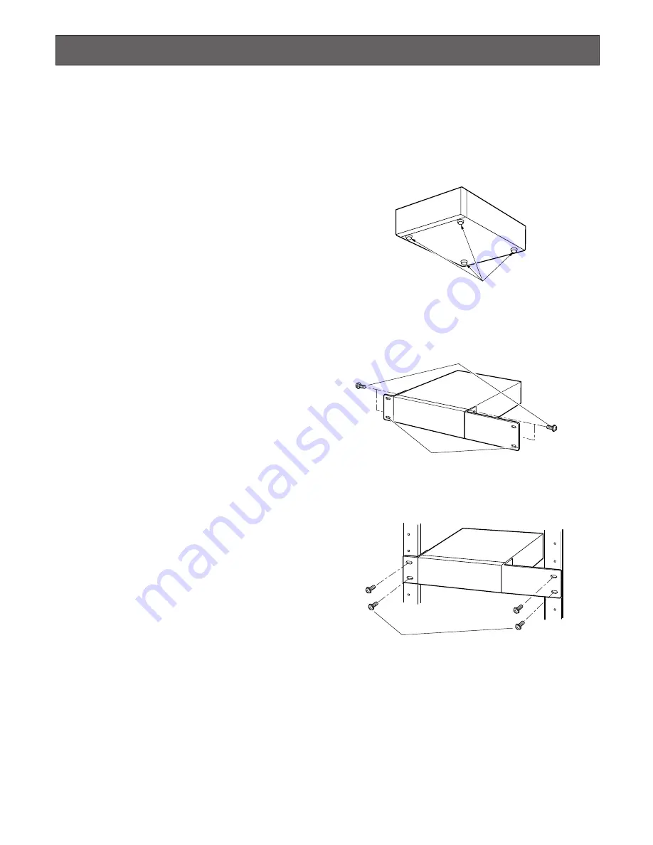
1. Remove the four rubber feet from the bottom of the unit

using a flathead screwdriver. 

2. Place the optional rack mounting brackets on both

sides of the unit and tighten with the four screws. 

3. Install the unit with the rack mounting brackets in the

rack by using four rack mounting screws.

Cautions:

• Make a space of 1U {44 mm, 1.73"} between the units

for ventilation, and install them in the rack as low as
possible.

• Keep the temperature in a rack below 45 °C {113 °F}.
• Install a fan in the rack when the ambient temperature is

above 30 °C {86 °F}.

• Do not block the ventilation openings or slots on the

cover to prevent the unit from overheating.

Remove the rubber feet.

Mounting screws for rack mounting brackets

Rack mounting brackets

Rack mounting screws

Summary of Contents for WJND200 - NETWORK DISK RECORDER

Page 1: ...ct please read these instructions carefully and save this manual for future use Network Disk Recorder WJ ND200 ERROR REC OPERATE TIMER ALARM ALARM SUSPEND BUZZER STOP LINK ACT MIRROR HDD1 HDD2 Network Disk Recorder Installation Guide Model No WJ ND200 ...

Page 2: ...ng heeft voldoet aan de volgende normen of andere normatieve documenten overeenkomstig de bepalingen van Richtlijnen 73 23 EEC en 89 336 EEC Vi erklærer os eneansvarlige for at dette produkt som denne deklaration omhandler er i overensstemmelse med standarder eller andre normative dokumenter i følge bestemmelserne i direktivene 73 23 EEC og 89 336 EEC Vi deklarerar härmed värt fulla ansvar för att...

Page 3: ...ICAL INAC CURACIES OR TYPOGRAPHICAL ERRORS CHANGES ARE ADDED TO THE INFORMATION HEREIN AT ANY TIME FOR THE IMPROVEMENTS OF THIS PUBLICATION AND OR THE CORRESPONDING PRODUCT S The serial number of this product may be found on the sur face of the unit You should note the serial number of this unit in the space provided and retain this book as a permanent record of your purchase to aid identification...

Page 4: ... your outlet consult an electrician for replacement of the obsolete outlet 10 Protect the power cord from being walked on or pinched particularly at plugs convenience receptacles and the point where they exit from the apparatus 11 Only use attachments accessories specified by the manufacturer 12 Use only with the cart stand tripod bracket or table specified by the manufacturer or sold with the app...

Page 5: ...ront View 10 Rear View 12 Rack Mounting 13 Connection 14 How to connect the unit with PCs and cameras 14 Connection between cameras and PCs 15 How to Use the Terminals of the ALARM CONTROL Connector 17 How to Use the Terminals of the ALARM Connector 21 Turn On Off the Power of the Unit 23 Turn on the power of the unit 23 Turn off the power of the unit 23 Check the IP Address 24 How to Replace the ...

Page 6: ...tion may occur and will reach their lifetime of oper ation in case they are used at temperature of 25 C 77 F It is recommended to keep the ambient operating temperature below 25 C 77 F to prevent data loss from disk clashes etc and replace them after around 18 000 hours as indication of operation When hard disk drive trouble occurs replace it immedi ately Consult your dealer for servicing Hard dis...

Page 7: ...sk If this happens do not turn on the power of the recorder and leave the recorder for around 2 hours Wait until the dew evaporates in any of the following cases The recorder is placed in an extremely humid place The recorder is placed in a room where a heater has just been turned on The recorder is moved from an air conditioned room to a humid and high temperature room When the unit has not been ...

Page 8: ...modes by oper ating an external switch External timer recording It is possible to perform recording automatically using an external timer Event recording At an event occurrence such as an alarm signal is sup plied the recording mode recording rate can be changed to high rate to record pictures Removable disk Two removable disks are provided and they can be removed and inserted easily and quickly o...

Page 9: ...mes of companies and products contained in these operating instructions may be trademarks or registered trade marks of their respective owners As you will use this product connected to a network your attention is called to the following security risks 1 Leakage or theft of information through this product 2 Use of this product for illegal operations by persons with malicious intent 3 Interference ...

Page 10: ...ghts when the alarm output stops The blinking or lighting indicator will go off when the alarm is reset Refer to the operating instructions PDF about the alarm y Buzzer stop button BUZZER STOP Press this button to stop the buzzer that started sound ing at an alarm error occurrence Refer to the operating instructions PDF about the alarm error u Alarm suspension indicator ALARM SUSPEND Lights when t...

Page 11: ...range when the unit is mounting the hard disk or when the hard disk is in the process of shutdown Blinks green when the mounted hard disk is unformat ted Lights orange when recording is being performed Blinks red when the disk replacement warning is being issued Lights red when the disk space is running out Refer to the setup instructions PDF for further informa tion about the disk replacement war...

Page 12: ...nnec tor when controlling this unit using an external device or when controlling an alarm device such as a buzzer or a lamp r Signal ground terminal SIGNAL GND t Power switch POWER y Power cord inlet AC IN Connect the power cord to this inlet After connecting the power cord fix the power cord using the provided brace as follows 1 Attach the provided brace to the rear panel of the unit 2 Fix the po...

Page 13: ... the unit using a flathead screwdriver 2 Place the optional rack mounting brackets on both sides of the unit and tighten with the four screws 3 Install the unit with the rack mounting brackets in the rack by using four rack mounting screws Cautions Make a space of 1U 44 mm 1 73 between the units for ventilation and install them in the rack as low as possible Keep the temperature in a rack below 45...

Page 14: ... PCs and cameras Connect cameras and PCs using the network port on the rear of the unit The following are descriptions of how to connect the unit with PCs and cameras using a hub as shown in the illustration below Images video signals from cameras will be supplied to the network port and supplied to PCs from the unit ON OFF POWER ALARM ALARM CONTROL SIGNAL GND 10 100BASE T AC IN Hub Network Camera...

Page 15: ...ly without using a hub connect them using a cross LAN cable Connecting PCs using an ADSL line Note When using a router MPEG 4 images sometimes may not be displayed Refer to the network administrator for how to con figure the settings of the router ON OFF POWER ALARM ALARM CONTROL SIGNAL GND 10 100BASE T AC IN HUB This unit Network Camera Network Camera ADSL router ADSL line PC PC Internet LAN cabl...

Page 16: ...AC IN ON OFF POWER ALARM ALARM CONTROL SIGNAL GND 10 100BASE T AC IN Unit no 1 Unit no 2 Hub Hub Network Camera Network Camera Network Camera Network Camera PC PC LAN cable Not provided 10BASE T 100BASE Tx category 5 straight LAN cable Not provided 10BASE T 100BASE Tx sategory 5 straight ...

Page 17: ...n DHCP IP address expiration Open collector output 24 V max 100 mA 1 Alarm reset input 2 Emergency recording input 3 4 Earth Grounding 5 Available disk space warning output Signal output upon detection of a HDD error 6 HDD error output Signal output upon detection of a camera error 7 Camera error output Signal output upon detection of a unit error 8 Error output Signal output upon completion of ou...

Page 18: ...the Auto Adjust Time function When Auto Adjust Time of Time Date of System on the setup menu is set to MASTER Time Adjust Output becomes available and the clock of this unit can be applied to other units The time adjust output signal will be supplied from pin no 20 to other unit at the time set for Time Date System Time Date Time Date Terminal block of other unit Time adjust output Earth ALARM CON...

Page 19: ... Important When SLAVE is selected the auto time adjustment function works differently depending on the recording status as fol lows 1 When event recording is performed on any camera channel ALARM CONTROL Terminal block of other unit Earth Sensor input Alarm input Alarm reset input Series recording input Time adjust input Earth Alarm output Alarm reset output Alarm recording During recording Disk B...

Page 20: ...wer system UPS Then the power supply to this unit can be suspended Connection of the control output When an alarm device such as a buzzer or a lamp is connected the signal output from Pin Nos 15 18 can be used to notify the status by sounding a buzzer or lighting a lamp The following example is of a connection with the HDD error output pin no 16 3 6 Alarming device Relay etc Earth HDD error output...

Page 21: ...wn below The connector to be used should be compatible with the pin configu ration Pin Configuration The pin array is different from other disk recorders Make sure that the connection is correct referring to the following Pin No q Signal Operation Event action will be performed accord ing to the settings Non voltage make contact input 100 mA 5 V pull up Alarm signal output at an event occur rence ...

Page 22: ...Alarm reset input Emergency recording input Available disk space warning output HDD error output Camera error output Error output Outage processing end output Time adjustment I O Alarm suspension input Outage detection input External recording mode changeover Active time 100 ms or more The time set on the setup menu Until the network error is cleared or until the ERR button on the operation window...

Page 23: ... of System on the setup menu to stop the recording currently being per formed Refer to the setup instructions PDF for further information When images are currently being played stop playback Click the STOP button displayed when the HDD tab is selected Refer to the setup instructions PDF for further information Note It is necessary to start recording after the power is turned on when recording had ...

Page 24: ...55 0 Check the IP Address The following network settings can be checked on the setup menu Basic Setup Comm Refer to the setup instructions PDF for further information about the setup menu DHCP IP address Subnet mask Gateway HTTP port The default network settings of each port are as follows Network Port Maintenance Port ...

Page 25: ...tart blinking orange When shutdown of the hard disk is complete the blinking will stop and the hard disk is ready to be removed Important When the USE button of the hard disk on which record ing is currently being performed is pressed recording will be continued on the other disk In this case some images to be recorded may not be recorded for sever al seconds to change the disk for recording When ...

Page 26: ...n will light green Notes Once the hard disk is removed it is impossible to record on this hard disk even after inserting the hard disk again Only playback is available To record on this hard disk format it with this unit again Refer to the setup instructions PDF for further infor mation It is impossible to format a hard disk when the write pro tection is on for it Refer to the operating instructio...

Page 27: ... the unit Check if alarm input signals are properly input to the ALARM or ALARM CONTROL connector on the rear panel Check the settings of the ALARM connector Cannot turn on the power Alarm operations are not acti vated Page Problem 21 21 22 The error indicator blinks orange The unit stops because of the thermal error 6 Isn t the fan on the rear panel or the ventilation slots on the front side of t...

Page 28: ... Unplug the power plug from the AC outlet immediately and refer to qualified service personnel The power cord insulation is damaged The power cord plug and con nectors get hot during use The power cord gets hot when bent or stretched Check item Remedy Problem Check item Remedy Page Problem The respective HDD is faulty The HDD access indicator lights red 10 ...

Page 29: ...less 3 HIGH 5 V 12 V 6 3 mA max 4 52 kΩ 5 V pull up 100 mA make contact 5 200 mA max Dimensions Weight 270 mm W x 88 mm H x 360 mm D 10 5 8 W x 3 1 2 H x 14 1 4 D excluding rubber feet and projections WJ ND200 5 0 kg 11 lbs Standard Accessories CD ROM 1 pc Installation Guide this manual 1 pc The CD ROM contains the operating instructions PDFs The following are for installation Power Cord NTSC mode...

Page 30: ...c equipment please contact your dealer or supplier for further information Information on Disposal in other Countries outside the European Union This symbol is only valid in the European Union If you wish to discard this product please contact your local authorities or dealer and ask for the correct method of disposal For U S Canadian and Puerto Rican fields Panasonic System Solutions Company Unit...

Reviews: