Panasonic WJHDE300 - DIGITAL DISK RECORDER Conversion Manual Download Page 8


7

 Panasonic System Solutions


HDE300_SATAConversionGuide_B

WJ-HDE300 S-ATA conversion guide


  Maintenance guide

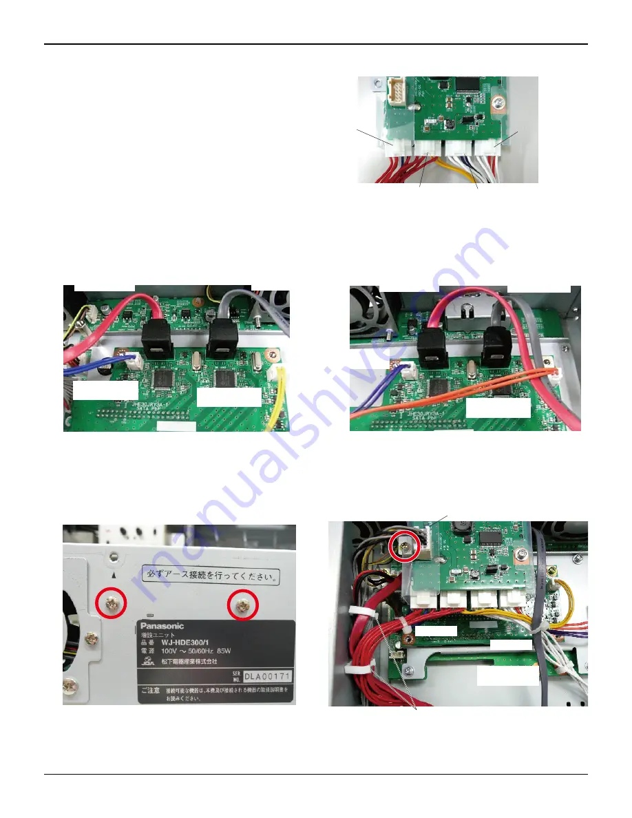
(22) Connect four power cables to the power distribution 

board.

(23) Connect the S-ATA cables and power cables to the S-ATA board as shown below.

(24) Fix the power distribution board to the main unit with three screws (one at the top, and two at the rear), and connect the connector 

CN100. Pass the red power cables for HDD1 and HDD2 through a clamp, pass the S-ATA cables for HDD1(red) through two clamps, 
and fasten the red power cables with a cable tie as shown below. Fasten the white power cables and the S-ATA cables for HDD2(gray) 
with a cable tie as shown below. 

CN105

for Power Cable

(White : Orange)

CN104

for Power Cable

(White : Purple)

CN103

for Power Cable

(Red : Yellow)

CN102

for Power Cable

(Red : Blue)

SATA HDD3

(Red )

 Power cable

(Purple)

SATA HDD4

(Gray )

Power cable

(Orange)

SATA HDD1

(Red )

SATA HDD2

(Gray )

Power cable

(Yellow)

 Power cable

(Blue)

CN100

Cable tie

Cable tie

Pass S-ATA cables (red for HDD1) 
through two clamps

SATA HDD2

(Gray )

Summary of Contents for WJHDE300 - DIGITAL DISK RECORDER

Page 1: ...Digital Disk Recorder Extension Unit WJ HDE300 S ATA conversion guide 1 Sept 2008 Panasonic System Solutions WJ HDE300 Extension Unit...

Page 2: ...02 S ATA Gray Power cable Red Yellow 1 each K1V313Y10003 S ATA Gray Power cable White Orange K1V313Y10004 S ATA Red Power cable Red Blue K1V313Y10005 S ATA Red Power cable White Purple S ATA board mou...

Page 3: ...icity accumulating in your body Ensure that the HDD is protected against static charge by placing disks on a antistatic mat or a conductive bag during the conversion work 1 Remove two screws fixing th...

Page 4: ...the recorder not recognizing the extension unit or the drives HDD 1 slot HDD1 HDD 2 slot HDD2 HDD 3 slot HDD3 HDD 4 slot HDD4 5 Remove six screws fixing the metal plate and then remove the metal plate...

Page 5: ...ach fixing the HDDs the sleeves and dampers and then remove the HDDs 9 Remove 11 screws that fix the top cover to the main unit and then remove the top cover 10 Disconnect two HDD fan connectors from...

Page 6: ...30 mm from the main board 14 Remove four screws each fixing the HDD mounting chas sis and remove two HDD mounting chassis 15 Disconnect the ATA cables from the main board 16 Remove two angle fixing s...

Page 7: ...gonal spacer 22 mm to the S ATA board mounting angle 20 Insert two S ATA boards into the ATA connectors on the main board and fix them with two screws each Note Circled tapped holes on the S ATA conne...

Page 8: ...les for HDD1 and HDD2 through a clamp pass the S ATA cables for HDD1 red through two clamps and fasten the red power cables with a cable tie as shown below Fasten the white power cables and the S ATA...

Page 9: ...e length of S ATA cables and secure them as shown below 27 Fix two HDD mounting chassis to the main unit with four screws each from the top and two screws at front There are four holes on the front bu...

Page 10: ...0 Install new HDDs on the HDD mounting brackets with four screws each Refer to the Operating Instructions for detail Notes When disconnecting the ATA cables pull the pull ring slowly and straightforwa...

Page 11: ...connectors have been inserted com pletely 33 Replace the SW label on the front chassis with a new one as shown right 34 Fix the metal plate with six screws in the reverse order of the removal 35 Inst...

Page 12: ...order of the removal 37 Attach the S ATA label large for top to the top panel Attach the S ATA label small for front to the front panel Note The new HDDs need to be formatted before operation Refer to...

Reviews: