background image

25

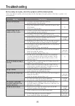
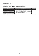
Before asking for repairs, check the symptoms with the following table.

Contact your dealer if a problem cannot be solved even after checking and trying the solution in the table or a problem is not 
described below.

Symptom

Cause/solution

Ref. pages

Power is not turned on.

•  Is the power plug connected to the outlet firmly?


Confirm the cable is firmly connected.

•  Check if the power cord is properly inserted into the power socket 

of the recorder.


Check if it is connected firmly.

19

Camera images are not 
displayed on the monitor.

•  Is the lens cap of the camera detached from the camera?


Check whether the lens cap is removed.

•  Is the power of the camera and connected devices on?


Check whether the power is supplied to the camera and the devices.

•  Confirm that the cables are connected correctly and firmly.


Confirm the cables are firmly connected.

Installation 

Guide

•  Depending on the HDMI monitor, it may not be displayed properly. 

Turn the monitor off and on and check whether it is displayed.

•  Is the monitor luminance appropriately adjusted, or is the contrast 

appropriately adjusted?


Check whether the settings are appropriate.

•  Users who have logged into the system may not be authorized to 

display the images from cameras.


Check the user level settings of these users.

Operating 

Instructions

•  Have the licenses of the additional camera kit been registered? 


If you have increased the camera connection number, and the 
camera image on the monitor does not appear, please use the 
browser on your PC.

10

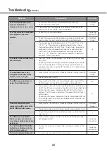
Part of the displayed image is 
missing.

•  This phenomenon is caused by dispersion of display area on the 

monitor. This is not a malfunction.

•  When a function to automatically enlarge the images in the con-

nected monitor is enabled, some part of the images may not be 
displayed depending on the photographic subject.

Image is blurred.

•  Is the lens of the camera soiled with dirt or dust?


Check whether the lens of the camera is clean.

Cannot open the setup menu.

•  Users who have logged into the system may not be authorized to 

display the setup menu.


Check the user level settings of these users.

Operating 

Instructions

•  Isn’t it the sub monitor you are currently operating?


The setup menu cannot be displayed on the sub monitor.

Installation 

Guide

The images or embedded 
characters displayed on the 
monitor look blurry.

•  Depending on the photographic subject or HDMI monitor that is 

connected, images or embedded characters may look blurry. This 
phenomenon is not trouble.

No alarm action is taken.

•  Check if alarm input signals are properly input to the ALARM/

CONTROL connector at the rear panel.

Installation 

Guide

•  Are the settings of the alarm connector appropriate?

Operating 

Instructions

•  Is "Off" or "Recording only" selected for "Mode"?


Check whether the settings are appropriate.

Operating 

Instructions

Troubleshooting

Summary of Contents for WJ-NX400K

Page 1: ...ead these instructions carefully and save this manual for future use The model number is abbreviated in some descriptions in this manual Important Information Network Disk Recorder Model No WJ NX400K...

Page 2: ...rried out in accordance with all applicable installation rules The connections should comply with local electrical code CAN ICES 3 A NMB 3 A For Canada The model number and serial number of this produ...

Page 3: ...t be used until a replacement cover is obtained A replacement fuse cover can be purchased from your local Panasonic Dealer IF THE FITTED MOULDED PLUG IS UNSUITABLE FOR THE SOCKET OUTLET IN YOUR HOME T...

Page 4: ...lt an electrician for replacement of the obso lete outlet 10 Protect the power cord from being walked on or pinched particularly at plugs convenience receptacles and the point where they exit from the...

Page 5: ...10 About HDD Unit 10 About Additional Camera Kit option 10 About Secure Communication Kit option 11 Precautions 12 Major operating controls and their functions 15 Front view 15 Inside the front cover...

Page 6: ...m this recorder This recorder can connect the extension unit WJ HXE400 option up to five and support up to 54 HDDs This recorder supports connection with a monitor equipped with the HDMI High Definiti...

Page 7: ...ives and displays the event and error information compatible cameras and their versions Refer to the Panasonic support website https security panasonic com support for latest information about the com...

Page 8: ...meets the following system requirements OS Microsoft Windows 7 1 Microsoft Windows 8 1 Microsoft Windows 10 Web browser Windows Internet Explorer 11 32 bit CPU Intel CoreTM i7 860 Memory 4 GB or more...

Page 9: ...CLUDING WITHOUT LIMITATION DIRECT OR INDIRECT SPECIAL CONSEQUENTIAL OR EXEMPLARY ARISING OUT OF OR RELATING TO THE PRODUCT 2 ANY INCONVENIENCE LOSS OR DAMAGE CAUSED BY INAPPROPRIATE USE OR NEGLIGENT O...

Page 10: ...ion continued Network security As you will use this unit connected to a network your attention is called to the following security risks Leakage or theft of information through this unit Use of this u...

Page 11: ...not available when registering the additional camera kit license Display of the camera image on the main and the sub monitors connected to the recorder Camera images will be displayed on the web brows...

Page 12: ...ock Do not connect disconnect the power plug with wet hands Failure to observe this may cause electric shock Avoid doing anything that can damage the power cord plug Do not damage modify forcefully be...

Page 13: ...operation and head and motor deterioration may occur after around 30 000 hour of operation They will reach the end of their lifetime after 30 000 hours of operation if they have been used at the reco...

Page 14: ...utomatically reboot to continue recording When the software of this product has detected the internal error and reboot becomes necessary Disclaimer of warranty on recoded data Panasonic assumes no res...

Page 15: ...es the status access failure of the respective hard disk drive Page 17 Basically each indicator will indicate the status of the respective HDD units HDD unit 1 to 9 but each indicator will be the same...

Page 16: ...y default to from the IP address display of the recorder If an error message is displayed on the LCD the message will be deleted if this button is pushed and it will return to the date time display Fr...

Page 17: ...ghts red Indicates that the respective hard disk drive is faulty which can be recovered by replacing the hard disk drive In the RAID1 RAID5 mode it indicates that the respective hard disk drive is the...

Page 18: ...ction ports on the front Use either of them Network port PC port PC Connect the recorder with a PC via a network compati ble with 10BASE T 100BASE TX or 1000BASE T Use this port when the cameras and t...

Page 19: ...ord 15 cm to 20 cm 5 7 8 to 7 7 8 inches Tighten the power cord at 15 cm to 20 cm 5 7 8 to 7 7 8 inches from the connector and fix it to the clamp mount Cut the unnecessary part of the power cord clam...

Page 20: ...Manager 1 High Operator 2 Viewer 3 Logged out 4 Low When the two or more users at the same level perform the same operation the recorder will be controlled in accordance with the latest operation Defa...

Page 21: ...tall the HDD units in order starting with disk slot 1 Once the operation has started in RAID1 RAID5 or RAID6 mode do not change the position of the HDD unit If they are changed it may become impossibl...

Page 22: ...ort the recorder 1 Remove all the HDD units in the recorder or fit the HDD unit holding brackets and fix them with screws 2 Put the recorder between the cushions and insert together into the packing b...

Page 23: ...without knocking against HDD units which are already inserted Push the upper part of the lever securely until it hits the protruding section at the back side of disk slot top and then turn down the le...

Page 24: ...r up while holding down the removal knob on the HDD unit Pull the HDD unit out from the HDD slot Pull the HDD unit out carefully so as not to drop it and handle it gently so as not to give it a shock...

Page 25: ...licenses of the additional camera kit been registered If you have increased the camera connection number and the camera image on the monitor does not appear please use the browser on your PC 10 Part o...

Page 26: ...indicator does not light Make sure that the HDD unit is inserted all the way into the HDD slot Installation Guide The hard disk drive is faulty The HDD access indicator is being lit red blinking red M...

Page 27: ...s damaged The power cord connector or power plug is damaged This may result in electric shock or a fire Unplug the power plug from the AC outlet immediately and refer to qualified service personnel Th...

Page 28: ...when 3 or more hard disk drives are installed RAID6 Available only when 4 or more hard disk drives are installed Input Output Video Video output connector 1 V p p 75 1 BNC Monitor HDMI connector HDMI...

Page 29: ...lector output 24 V DC max 200 mA max 3 5 V 0 5 V 200 mA max 4 High ON DC 5 V Low OFF DC 0 V Option as of December 2017 Additional Camera Kit license for 32 cameras WJ NXE40 WJ NXE40W Secure Communicat...

Page 30: ...Newark NJ 07102 5490 Panasonic Canada Inc 5770 Ambler Drive Mississauga Ontario L4W 2T3 Canada 905 624 5010 www panasonic ca Panasonic Corporation 2017 L1116 4127 PGQP2334VA For Europe and other coun...

Reviews: