background image

47

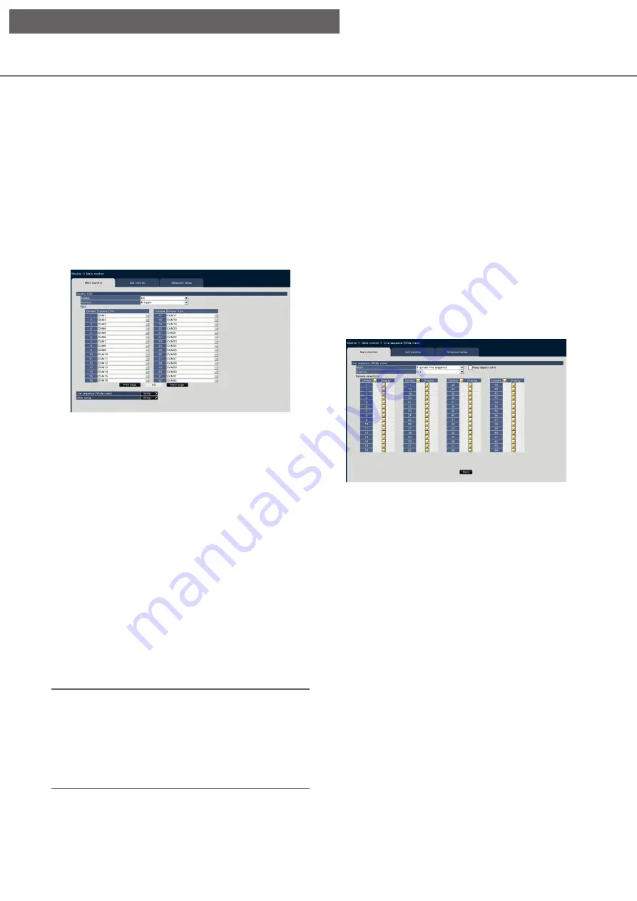
Configure the settings relating to monitors [Monitor]

The settings relating to the display of the main monitor or sub-monitor connected to the recorder are config-
ured on the setup menu - the "Advanced setup" - the "Monitor" page.
The settings relating to image switching such as multiscreen display and sequence display of live images are 
also configured on this page.
The "Monitor" page has 3 tabs; the [Main monitor] tab, the [Sub monitor] tab and the [Advanced setup] tab. The 
settings relating to the display of the web browser can be set on the [Web browser] tab of the "Monitor" page 
on the setup menu of the web browser. (

 Page 195)

Set up the main monitor [Main monitor]

Perform settings relating to the main monitor display such as the display position of the camera title.

 Camera title

[Display]

Determine whether or not to display the camera title 
on the main monitor.

On: Displays the camera title.
Off: Does not display the camera title.

Default:

 On

[Position]

Select the position to display the camera title on 
images.

L-Upper/ L-Lower/ R-Upper/ R-Lower

Default:

 R-Upper

[Camera title]

Enter a camera title to display for each camera using 
the on-screen keyboard (

 Installation Guide  page 

8). (Up to 16 characters)

Note:

• When using together with the date and time dis-

play to be set on the camera (

 Page 18) or 

OSD (Display Title, 

 Page 19), adjust the posi-

tion to be displayed to not to overlap with them.

• The camera title configured on this setting will not 

be embedded on recorded images.

 Live sequence (Wide view)

Set the sequence of the wide view screen on the 
main monitor.
The following live sequence (Wide view) screen will be 
displayed when the [Setup >] button is clicked.

[Mode]

Select a screen pattern of the sequence.

1-screen live sequence/4-screen live sequence/ 
9-screen live sequence/16-screen live sequence

Default: 

1-screen live sequence

[Keep aspect ratio]

Select whether to change the aspect ratio of the dis-
played area if the aspect ratio of the image is different 
from the displayed area.

Checked: Keep aspect ratio (Does not change the 

ratio automatically).

Not checked: Does not keep aspect ratio 

(Changes the ratio automatically).

Default:

 Not checked

[Duration]

Set the interval (duration) for switching camera 
images.

3 s/ 5 s/ 10 s

Default:

 5 s

[Setup via recorder's main monitor]

Summary of Contents for WJ-NX400G-54000T6

Page 1: ...this manual for future use The model number is abbreviated in some descriptions in this manual WJ NX400K GJ is the same model as the Network Disk Recorder WJ NX400K G Operating Instructions Network Disk Recorder Model No WJ NX400K WJ NX400K G WJ NX400K GJ Network Disk Recorder WJ NX400 1 2 3 4 5 6 7 8 9 ...

Page 2: ...Maintenance 64 Check the system information such as the version System information 64 Confirm the hard disk drive information HDD information 65 Configure the settings and operations relating to the system System management 67 Register the licenses for the recorder and the additional camera Registration of license 70 Manage the hard disk drives HDD management 72 How to display the HDD management p...

Page 3: ...atus display area 165 Download operation area 166 CAM tab 166 HDD tab 167 Monitor live images 168 Display images on a 1 screen 168 Display images on a 4 screen multiscreen 169 Operate the camera 170 Panning Tilting 170 Zooming 170 Focus adjustment 171 Iris brightness adjustment 171 Register preset positions 171 Move to preset positions 171 Auto mode AUX Wiper 172 Event function 173 Action to be ta...

Page 4: ...de The external appearance in the document may differ from the actual product within no influence range on operation due to improvement of the product Abbreviations The following abbreviations are used in this manual Microsoft Windows 8 1 is described as Windows 8 Microsoft Windows 7 is described as Windows 7 Windows Internet Explorer 11 is described as Internet Explorer Network cameras are descri...

Page 5: ...recorded image The playback or audio out put may be paused some ten seconds after the start of the playback depending on the volume of recorded image data If the audio output stops pause playback and replay it again When the frame rate is set to 25 ips 60 ips recorded images may not be played smoothly If the recorder cannot continue playback due to a large load it stops the playback and returns to...

Page 6: ... Sub stream recording Re encoding transmission A part of setup menu operation The main monitor displays not a camera image but a special menu The sub monitors turn black When using the web browser If the camera is set to high frame rate and high resolution update of images may take time or images may be displayed intermittently If the camera is used with the following settings the above may be imp...

Page 7: ...ubject has depth When configuring the motion detection settings check the function performance both in daytime and at night after appropriately configuring the area settings and the sensitivity settings according to the camera installation conditions and possible movement of subjects When the detection function does not work or false detection occurs use a sensor separately Refer to the operating ...

Page 8: ...es on the HDD The following recording operations are available Schedule recording Recording that is automatically performed at the designated time range on the desig nated day s of the week Event recording Recording that is automatically performed when an event occurs such as terminal alarm camera site alarm command alarm etc Emergency recording Gives priority to recording video and audio at emerg...

Page 9: ...the desired button on the setup menu Note The setup menu can be displayed by clicking the Setup button on the operation panel of the operation screen Date Language button Displays the Date Language page Perform settings such as date time and daylight saving time Camera button Displays the Camera page Perform registration and setup of network cameras REC event button Displays the REC event page Con...

Page 10: ...14 03 01 Mmm dd yyyy Mar 01 2014 dd Mmm yyyy 01 Mar 2014 mm dd yyyy 03 01 2014 dd mm yyyy 01 03 2014 Default Mmm dd yyyy WJ NX400K dd mm yyyy WJ NX400K G Time Select a time display format Example 3 o clock in the afternoon 24 h 15 00 00 12 h 03 00 00 PM Default 12 h WJ NX400K 24 h WJ NX400K G Time zone Select the time zone and shift to from daylight saving time Set time zone Select your time zone ...

Page 11: ... time adjustment Select a method of auto clock adjustment from the following Off Does not adjust the time automatically Slave Receives a signal from the ALARM CON TROL connector on the rear panel of the recorder and adjusts the clock When the sig nal is received and if the clock is within 29 minutes the hour the time will be adjusted to 00 minutes 00 seconds Master Outputs a signal from ALARM CONT...

Page 12: ... is clicked the Registered information window opens to edit the settings Page 15 In the event of communication trouble with the cam era one of the following error messages is displayed for Error information Connection error The communication with the camera disconnected Authentication error The user authentication of the camera failed Camera error The response from the camera is incorrect Note Whe...

Page 13: ...ed when the camera has been replaced by another one Added Displayed when the camera connection is added to the recorder Registered Displayed when the camera has already been registered Lost Displayed when the registered camera is not detected Blank No camera is detected IP address Displays the IP addresses configured for the detected cameras Auto addressing The IP addresses of the cameras whose ch...

Page 14: ...r camera administrator is selected in the Settings you cannot select cameras whose administrators have already been registered Transmission button Transmit the settings to the camera Once transmis sion is completed and the setting has been applied to the camera OK will be displayed in the Results field If the display reads Authentication error etc the camera connection or the setting may have fail...

Page 15: ...ive display browser display H 264 1 Sub stream recording by compression of H 264 live multi screen display H 264 2 Recording by compression of H 264 or H 265 1 screen live display browser display H 264 1 H 264 3 H 264 4 H 265 1 H 265 3 H 265 4 Sub stream recording by compression of H 264 or H 265 live multi screen display H 264 2 H 265 2 When selecting MJPEG for Compression the live image transmis...

Page 16: ...tain the latest camera image after interchanging cameras Back button Save the settings and return to the Camera registra tion tab Table to delete To delete registration information or remove a previ ously connected camera either select the camera number and click the Delete button or delete the IP address of the respective camera Auto model number acquisition Click the Execute button to acquire th...

Page 17: ...he settings of some models of Panasonic cameras only can be configured Refer to the readme txt on the provided CD ROM about the supported cameras Some functions are not supported depending on the models of the connected cameras For further information about detailed specifications refer to the operat ing instructions of the cameras in use It is impossible to check the current settings using this r...

Page 18: ...o display the date time on the images If the setting is to be transmitted to the camera mark this item to select the display position L Upper L Lower R Upper R Lower Note The position to display the title edited on Display Title Page 19 is the same as the Position selected here to display the date time edited on Date time display Camera selection Select the camera to which the date time display se...

Page 19: ...ng the on screen keyboard Installa tion Guide Page 8 Up to 16 alphanumeric char acters Available characters 0 9 A Z Camera title Display the camera title registered on the Main monitor tab of the monitor page Page 47 Copy button The camera title registered on the Main monitor tab of the monitor page can be used as display title Clicking this button will copy the camera title to the Display Title f...

Page 20: ...n images are viewed Off All the indicators will light off Camera Selection Select the camera to which the Indicator setting is to be sent Mark the checkbox of the camera to which the setup information is to be transmitted Transmission button Transmit the setting of the Indicator to the camera Once transmission is completed and the setting has been applied to the camera OK will be displayed in the ...

Page 21: ...detected Burst tolerance level Select the allowance of Max bit rate per client for the H 264 bit rate from the following when the trans mission priority is Advanced VBR High Middle Low Control time period Select the period of controlling H 264 bit rate to be recorded from the following 1 h 6 h 24 h 1 week Priority setting Set which to prioritize the Frame rate or the Image quality when the transmi...

Page 22: ... of the camera is detected Camera Selection Select the camera to which the setting of the Refresh interval is to be sent Mark the checkbox of the camera to which the setup information is to be transmitted Transmission button Transmit the setting of the Refresh interval to the camera Once transmission is completed and the setting has been applied to the camera OK will be displayed in the Results fi...

Page 23: ...l Camera Selection Select the camera to which the setting of the Upside down is to be sent Mark the checkbox of the camera to which the setup information is to be transmitted Transmission button Transmit the setting of the Upside down to the camera Once transmission is completed and the setting has been applied to the camera OK will be displayed in the Results field If the display reads Authentica...

Page 24: ...mera Selection Select the camera to which the setting of the Image rotation is to be sent Mark the checkbox of the camera to which the setup information is to be transmitted Transmission button Transmit the setting of the Image rotation to the camera Once transmission is completed and the setting has been applied to the camera OK will be displayed in the Results field If the display reads Authenti...

Page 25: ... The pan tilt flip function will not work Camera Selection Select the camera to which the setting of the Pan tilt flip is to be sent Mark the checkbox of the camera to which the setup information is to be transmitted Transmission button Transmit the setting of the Pan tilt flip to the cam era Once transmission is completed and the setting has been applied to the camera OK will be displayed in the ...

Page 26: ...ynamic function will work When On is selected the tone level will be com pensated to emphasize the sensitivity Off The super dynamic function will not work Camera Selection Select the camera to which the setting of the Super Dynamic is to be sent Mark the checkbox of the camera to which the setup information is to be transmitted Transmission button Transmit the setting of the Super Dynamic to the ...

Page 27: ...o which the setting of the Adap tive black stretch is to be sent Mark the checkbox of the camera to which the setup information is to be transmitted Transmission button Transmit the setting of the Adaptive black stretch to the camera Once transmission is completed and the setting has been applied to the camera OK will be displayed in the Results field If the display reads Authentication error etc ...

Page 28: ...ed by back light On Mask area will automatically be set Off Mask area will not be set automatically It is necessary to set mask areas manually Camera Selection Select the camera to which the setting of the Back light compensation BLC is to be sent Mark the checkbox of the camera to which the setup information is to be transmitted Transmission button Transmit the setting of the Back light compensat...

Page 29: ...e above For 60 Hz areas ELC The iris will automatically be controlled with the shutter speed adjustment to control light Camera Selection Select the camera to which the setting of the Light control mode is to be sent Mark the checkbox of the camera to which the setup information is to be transmitted Transmission button Transmit the setting of the Light control mode to the camera Once transmission ...

Page 30: ...ox of the camera to which the setup information is to be transmitted Transmission button Transmit the setting of the Auto slow shutter to the camera Once transmission is completed and the setting has been applied to the camera OK will be displayed in the Results field If the display reads Authentication error etc the camera connection or the setting may have failed Back button Click the button aft...

Page 31: ...ot bright Auto2 IR Light Use it at night time or when using near IR light source Auto3 Super Chroma Compensation SCC Use it if you want to keep the color image even if the light source is not bright Super Chroma Compensation SCC function keeps the color image under the lower illuminance than Auto1 Normal Note On Auto2 and Auto3 can be selected for cameras having Day Night electrical only but they ...

Page 32: ...sibility of people s faces and objects in motion Off Does not use the intelligent auto function On Uses the intelligent auto function Camera Selection Select the camera to which the setting of the Intelligent auto is to be sent Mark the checkbox of the camera to which the setup information is to be transmitted Transmission button Transmit the setting of the Intelligent auto to the camera Once tran...

Page 33: ...ion sensitivity To transmit the settings to the camera mark this item and select either of the following 1 Low 15 High Camera Selection Select the camera to which the setting of the VMD alarm is to be sent Mark the checkbox of the camera to which the setup information is to be transmitted Transmission button Transmit the setting of the VMD alarm to the cam era Once transmission is completed and th...

Page 34: ...thod Set the connection method for each camera RTP Connects with the RTP RTSP Connects with the RTSP It is used for local camera connection and others Internet mode Connects in the Internet mode It is used to connect remote cameras or for other connection Note The connection method will become valid for the Panasonic camera whose compression type is H 264 H 265 Setup via recorder s main monitor ...

Page 35: ...ing time will be set Within the same time table event recording has priority over schedule recording Schedule recording Mark the checkbox es if you want to carry out the schedule recording based on the set time bar Event recording Mark the checkbox es if you want to carry out event recording based on the set time bar The recorder does not record the image even if the alarm occurs during time in wh...

Page 36: ...emergency recording If a camera manufactured by other than Panasonic is used the value of Referenced recording days will not be displayed preceding an item indicates that the item has been changed on the Advanced recording setup page When configured to perform recording in high res olution and high quality recording may sometimes not be performed at the specified rate When there may be possibility...

Page 37: ... Default 0 s Important The pre event recording is only available for Camera 1 to Camera 64 The pre event recording available time becomes extremely short when the sub stream recording is on The pre event recording is available for Camera 1 to Camera 128 at the additional camera 96ch 128ch mode Note The actual recording time may sometimes be longer than the duration selected for this setting When t...

Page 38: ...hod Note When configured to perform recording in high res olution and high quality recording may sometimes not be performed at the specified rate Depending on the model of the camera the cam era may reboot when the image capture size is changed The reboot will be detected as a com munication error but that is not a malfunction Rate Frame rate Page 35 Note The 25 ips 50 ips 60 ips is available depe...

Page 39: ... the event recording and the emergency recording to Same as the basic Referenced recording days Page 36 Back button Click the button after completing the settings The screen returns to the Recording setup tab Check the pre event duration and availability of recording You will be able to check the pre event duration and availability of recording of each camera Clicking the Advanced button on the Re...

Page 40: ...xt Note If the time set for Output duration or Buzzer duration is longer than that set for Auto reset time the time set for Auto reset time will be applied Message display Select whether or not to display a message on a PC connected to a network when an alarm occurs On Display a message Off Does not display a message Default On Main monitor action While the main monitor is displaying the operation...

Page 41: ...tion It selects the display in which the main monitor action to be displayed Ctrl screen Displays in the Ctrl screen Wide view Displays in the Wide view Advanced event setup Configure advanced settings for individual alarm types terminal alarm camera site alarm and command alarm Clicking the Advanced button for each item will open the respective Advanced setup Setup via recorder s main monitor ...

Page 42: ...or record ing Default Camera number associated with the terminal number Note When many cameras are registered and All is selected for Recording camera the start of alarm recording may be delayed depending on the cameras It is recommended to perform pre event recording Preset Select the camera preset position 001 to 256 to which the camera is to be moved when an alarm sig nal is received If is sele...

Page 43: ...ent recording time Page 36 is shorter than alarm deactivation time set from the camera the event recording may not be done for alarms which continuously occur Set up command alarm Advanced command alarm setup Set up the action to be taken when a command alarm signal received from a PC that is connected via a net work protocol triggers command alarm Refer to the Set up terminal alarm Advanced termi...

Page 44: ...the HTTP port number the HTTPS port number the FTP port number and the port number of the port forwarding are unavailable 20 21 23 25 42 53 67 68 69 79 80 105 110 123 161 162 443 546 547 995 10001 10002 10003 10004 10005 10006 10007 Recording time of emergency recording Select a recording duration for the emergency recording 30 s 1 min 3 min 5 min 10 min 15 min 30 min Manual Records only while the...

Page 45: ... time set on the sched ule has arrived without communication between the camera and the recorder the SD memory backup will not be executed Do not set the SD memory backup function to the same camera from multiple network disk recorders The recording time of the acquired SD memory data will be time of the camera Adjust time of the camera and the recorder using the NTP function and the camera time a...

Page 46: ... band Special days Assign a schedule of another day individually as a special day For example if you set January 1st to Sunday the recording will be performed as on Sunday no matter which day of the week January 1st is actually on The following screen of the special day will be dis played when the Setup button is clicked Month Day Select a date that you want to set as a special day Day Select a da...

Page 47: ...pper R Lower Default R Upper Camera title Enter a camera title to display for each camera using the on screen keyboard Installation Guide page 8 Up to 16 characters Note When using together with the date and time dis play to be set on the camera Page 18 or OSD Display Title Page 19 adjust the posi tion to be displayed to not to overlap with them The camera title configured on this setting will not...

Page 48: ... view in association with whether the mouse cursor is dis played or hidden Stretch images to fit the areas in control screen display Mark the checkbox to enlarge the vertical size of images with the aspect ratio of 16 9 to fit into the image display area on the control screen Note If the image is expanded by this setting the cam era operation or the motion detection search in the image may not fun...

Page 49: ... on 32Screen without switching the screen Keep aspect ratio Select whether to change the aspect ratio of the dis played area if the aspect ratio of the image is different from the displayed area Checked Keep aspect ratio Does not change the ratio automatically Not checked Does not keep aspect ratio Changes the ratio automatically Default Not checked Duration Set the interval duration for switching...

Page 50: ... the sub monitor HDMI When the sub monitor is to be used and the check box is marked the error action will be taken if the sub monitor is disconnected or the power is off Note Depending on the monitor it may not be detected even if the power switch of the monitor is turned off Secret view Secret view is a function that causes the camera image displayed on a 1 screen or the selected cam era image o...

Page 51: ... in accordance with the recorder s network environment Enter in the same way as the IP address Default 255 255 255 0 Camera PC port 0 0 0 0 PC port Default gateway Select the address for the default gateway in accord ance with the recorder s network environment Enter in the same way as the IP address Default 192 168 0 1 Line speed Specify the line speed for data transmission Auto Line speed will b...

Page 52: ...namic DNS service designed for use with Panasonic Network Cameras Refer to the Viewnetcam com website http www viewnetcam com for further informa tion about the service When using the Viewnetcam com service Personal Product URL The URL of the camera registered for Viewnetcam com When accessing the menu again after performing the initial settings the temporary URL will be displayed Your account lin...

Page 53: ...sing the URL displayed beside Your account link When the URL is not displayed check that the recorder is being connected to the Internet exit the menu and display this tab again to check the information If access often fails due to the change in the global address of router set a smaller value for Access interval Procedure to register information for the Viewnetcam com service Other setup Click th...

Page 54: ...d audio if the network address of the desti nation is different from that of the recorder Default Off Port forwarding Click the Setup button to set the port forwarding Port forwarding Set whether to enable the port forwarding or not On Sets the port forwarding Off Does not set the port forwarding Port setup Set the port number of each camera between 1 to 65535 if the port forwarding is set Default...

Page 55: ... user name to be required for the authentica tion Enter up to 32 alphanumeric characters exclud ing listed in the description of Note Authentic method Password Enter the password to be required together with the user name for the authentication Enter up to 32 alphanumeric characters excluding listed in the description of Note An entered character for the password will be displayed as Note Availabl...

Page 56: ...not necessary change the default Default 1818 Retry Set the number of retry attempts for the transmission to the PC 0 8 times In steps of times Default 2 Note If the transmission to the PC fails increase the number of retry attempts Destination address Address1 Address8 Enter the addresses of the recipient PCs Enter the IP address or host name for Address1 Address8 The host name is available only ...

Page 57: ...sed from the Advanced setup menu the Network page of the setup menu Enter up to 255 alphanumeric characters including hyphens and periods Note Entering http is not necessary if the server name is entered Important It is possible to run the recorder as an NTP server to be referred by the cameras In this case set the port number of the camera to 123 Refer to the operating instructions of the connect...

Page 58: ... registered in the recorder Default Administrator Quick login Select On or Off to determine whether to enter or select the user name Off User name needs to be entered On Login by selecting a displayed user name Default Off Auto logout Set the time to wait until auto logout when no opera tions are made while displaying live images Off Does not logout to the recorder automati cally After 1 min After...

Page 59: ...and tilting can be performed Search and playback Recorded images can be played back and searched by VMD search Copy Recorded images can be copied to storage media such as a USB Alarm reset An alarm action can be canceled Error reset An error action can be canceled Setup Setup menus can be displayed and the settings can be configured Camera image display The image and audio data of all cameras can ...

Page 60: ...d operation level The maximum number of users that can be registered is 32 User name Enter the user name using the on screen keyboard Installation Guide Page 8 The user name must be between 1 32 characters including the half width alphanumeric and the symbol Password Enter the user password using the on screen key board Installation Guide Page 8 The password must be between 8 32 characters includi...

Page 61: ...n about each setting value Default 4Screen 1 Note When a monitor that is not selected in the Monitor Main monitor Other setup is set as the default screen 4Screen 1 will be dis played as the default screen When 9Screen 16Screen or any of wide view screen is selected the default screen on the web browser of the PC will be set to 4 screen with live images from camera 1 to 4 Registration button Selec...

Page 62: ...32 characters including the half width alphanumeric and the symbol Use at least two types of characters among alphabet numbers and symbols The registered password will be displayed as regardless of what is entered Important For enhanced security change the password on a regular basis Password Retype Enter the password that has been set for Password again for confirmation Level Display the operatio...

Page 63: ...numbers 0 0 0 0 and cannot be registered Level Select an operation level Refer to the User registration for the setting contents Default Manager Default screen Select a startup screen to be displayed after login on the web browser Cam 1 Cam 64 4Screen 1 4Screen 16 Default 4Screen 1 Registration button Registers the set host information as a new Edit host information Change or delete the registered...

Page 64: ... makes an error action to prevent failure or unsafety of equipment when tempera ture of internal parts such as HDD and CPU exceeds the specified temperature Extension unit information Displays the version information of the extension unit temperature information and recovery progress informa tion Click View button to display the following screen Note The recovery progress information is displayed ...

Page 65: ...hard disk drive and the running time of this product or the extension unit EXT1 EXT5 time range of the recorded images etc will be displayed Recorded time range Displays the time range of the images recorded on the hard disk drives Note When using in Mirroring mode RAID5 mode RAID6 mode Operation time will be displayed for each hard disk drive respectively while Capacity Status Recorded time range...

Page 66: ...alphanumeric and the symbol Use at least two types of characters among alphabet numbers and symbols The set pass word will be displayed as regardless of what is entered Important If you forget the password of the removed HDD you cannot play back the HDD in HDD viewer Retype password Enter the password that has been set for Password again for confirmation Save HDD viewer to USB medium Save HDD view...

Page 67: ...d by control mode Set a mode not to count the operation time of a hard disk drive HDD stand by control mode by temporar ily pausing HDDs other than those which are record ing or waiting for recording On Operates in the HDD stand by control mode Off Operates in the normal mode Default Off Note In Single mode it is effective when it consists of 3 or more HDD In Mirroring RAID1 mode it is effective w...

Page 68: ...the setting menu RESET HIGHEST TEMPERATURE The highest temperature information has been cleared About the network log The network error logs occurrence date time and error details will be displayed in list form Up to 100 logs are saved When more than 100 logs are filed the older logs will be overwritten by the newer logs In this case the oldest log is the first to be overwritten Refer to page 93 f...

Page 69: ...te Loads the software saved on a USB medium external storage device into the recorder to upgrade the firmware Click the Execute button to display the confirma tion window to start initializing Only an administrator can execute the firmware update Note Depending on the firmware to be updated it may take up to 30 minutes for upgrading leaving the start screen displayed Usage time varies depending on...

Page 70: ...uired to obtain the Regis tration Key The Activation Key Card provided with the recorder describes how to access the key man agement system Registration of license Register the Registration Key to operate the recorder and activate the extra functions Product Registration Key Enter the Registration Key obtained from the key management system When the Registration but ton next to the entry field is ...

Page 71: ...k of this product The time and date synchronization will be executed when the setting is completed after executing on the confirma tion window displayed by clicking the Execute but ton Synchronize the camera s settings with this unit Reconfigure the settings of all the registered cameras based on the setting information of this product The time and date synchronization will be executed when the se...

Page 72: ...cibly logs out any other users currently logged in to the recorder How to display the HDD management page Step 1 Click the HDD management button of the setup menu the Advanced setup menu The window with the administrator name and password entry fields will be displayed The win dow is also displayed when a user has already logged in as the administrator Step 2 Click the OK button after entering Adm...

Page 73: ...d disk drives are formatted It is necessary to initialize the HDD after replacing the HDD Important When a hard disk drive is formatted all the recorded images will be erased Step 1 Click the Execute button for Format HDD on the General tab HDD management page The window to format hard disk drives will be dis played Step 2 Check the hard disk drives to format in the Format field and click the Star...

Page 74: ...n be removed when OK is displayed in the Results field Click the Back button Note If a password is assigned for HDD viewer the HDD is also assigned with a password Add the HDD Add HDD Step 1 Click Execute on the Add HDD The HDD adding screen will be displayed Step 2 Check the HDDs to add and click the Start button The process is completed when OK is displayed in the Results field and the HDDs are ...

Page 75: ...ode When the operational mode of HDD is changed from the Mirroring mode to the Single mode the status of the HDD will turn to Playback only About the change of the HDD operational mode About the HDD operational mode Single mode Images and audio from the cameras will be recorded on each HDD in order Mirroring mode The same images and audio from the cameras will be recorded on 2 HDDs like HDD1 and H...

Page 76: ... camera Recording group Group1 Group2 Default Group1 Note If either Group1 or Group2 are set other than Unlimited for the recording group the recording group is displayed on each screen of the HDD management and of the HDD information of the Maintenance page Step4 Click the Recalculate button to calculate estimated required capacity of each group and display it Note When Unlimited is set the estim...

Page 77: ... The HTTPS encodes the access to the recorder and enhances the safety of the communication Connection Set the connection HTTP HTTPS The HTTP and HTTPS connec tions are available HTTPS The HTTPS connection is only available Default HTTP HTTPS HTTPS port number Set the port number used for the HTTPS 1 65535 Default 443 Note The following numbers the HTTP port number the site alarm receive port numbe...

Page 78: ...ic setup Remarks are the setting items configured on Easy Start are the setting items configured from the web browser are the setting items only configurable with web browser Menu Tab Setting item including those of the Advanced setup menu Available range Default Remarks Date Language Date time adjustment Date Time 2016 1 1 0 00 2037 12 31 23 59 20nn mm 1 0 00 nn and mm are calculated base on the ...

Page 79: ... Blank Port No Port No 80 Camera setup Date time display Display check box Checked Not checked Display drop down list Off On Position check box Checked Not checked Position drop down list L Upper L Lower R Upper R Lower Camera selection Checked Not checked Display title Display check box Checked Not checked Display drop down list Off On Display Title check box Checked Not checked Display Title Tex...

Page 80: ...Camera selection Checked Not checked Back light compensation BLC Back light compensation BLC Off On Camera selection Checked Not checked Light control mode Light control mode Outdoor scene Indoor scene 50 Hz Indoor scene 60Hz ELC Camera selection Checked Not checked Auto slow shutter Maximum shutter Auto slow shutter Maximum shutter Off 1 30 s Max 2 30s Max 4 30s Max 6 30s Max 10 30s Max 16 30s Ca...

Page 81: ...up Days to record Mon Tue Sun Time table1 Time table2 Off Time table1 Event recording Event recording duration 2 s 5 s 10 s 20 s 30 s 1 min 2 min 3 min 5 min 10 min 15 min Manual Ext 30 s Pre event duration 0 s 5 s 10 s 15 s 0 s Schedule to record Time table1 Schedule bar 00 00 24 00 Schedule bar 1 00 00 24 00 Schedule bar 2 Schedule bar 6 Time table1 Schedule recording Checked Not checked Checked...

Page 82: ...e bar 1 Schedule bar 6 Time table2 Schedule recording Checked Not checked Checked Time table2 Event recording Checked Not checked Checked Time table2 e Mail Checked Not checked Not checked Time table2 Panasonic alarm protocol Checked Not checked Not checked Display the schedule list Indication only Indication only Advanced recording setup Model Registered information will be displayed Registered i...

Page 83: ... Ext Ext Message display Off On On Main monitor action Off On On ACK RESET Off Event type Checked Not checked Terminal alarm Checked Camera site alarm Checked Command alarm Checked Display Ctrl screen Wide view Ctrl screen Advanced terminal alarm setup Mode Off Recording only Recording alarm action Recording alarm action Alarm log Save Not save Save Setup by terminal Recording camera Off Cam 1 Cam...

Page 84: ...Port No 1818 Recording time of emergency recording 30 s 1 min 3 min 5 min 10 min 15 min 30 min Manual Ext 30 s External recording setup Off Schedule1 Schedule16 Off SD backup rec Off On Off Smart coding GOP control Off On Advanced Off Sub stream recording Sub stream recording Off On Off Frame rate 1 ips 3 ips 5 ips 10 ips 10 ips Bit rate 64 kbps 128 kbps 256 kbps 384 kbps 512 kbps 768 kbps 768 kbp...

Page 85: ...Not checked Not checked 32 screen Checked Not checked Not checked 64 screen Checked Not checked Checked 1 screen pillar box Checked Not checked Not checked 4 screen pillar box Checked Not checked Not checked 9 screen pillar box Checked Not checked Not checked 12 screen pillar box Checked Not checked Not checked 16 screen pillar box Checked Not checked Not checked 3 screen unequally divided Checked...

Page 86: ...e Text will be entered G1 Group1 G8 Group8 Grouping G1 G2 G3 G4 G5 G6 G7 G8 Cam 1 Cam 16 G1 Cam 17 Cam 32 G2 Cam 33 Cam 48 G3 Cam 49 Cam 64 G4 Cam 65 Cam 80 G5 Cam 81 Cam 96 G6 Cam 97 Cam 112 G7 Cam 113 Cam 128 G8 Advanced setup Audio output camera Selected camera Cam 1 Cam 64 Up to Cam 128 in camera extension mode Selected camera Video format of sub monitor BNC NTSC PAL NTSC Other setup Detect a ...

Page 87: ...ill be entered Blank Password Text will be entered Blank Sender s address Text will be entered NWDR Security Off SMTP over SSL STARTTLS Off Destination address Address Text will be entered Blank Destination address Warning Checked Not checked Checked Destination address Alarm Checked Not checked Checked Panasonic alarm protocol Panasonic alarm protocol Port number to PC Port No 1818 Retry 0 8 2 De...

Page 88: ...ecked Viewer Not checked Logged out Not checked Fixed Error reset Checked Not checked Manager Checked Fixed Operator Checked Viewer Not checked Logged out Not checked Fixed Setup Checked Not checked Manager Checked Fixed Operator Not checked Viewer Not checked Logged out Not checked Fixed Camera image display Checked Not checked Manager Checked Fixed Operator Checked Viewer Checked Logged out Chec...

Page 89: ... port PC port MAC address Indication only Indication only IP address Indication only Indication only Line speed Indication only Indication only Network port Maintenance port MAC address Indication only Indication only IP address Indication only Indication only Line speed Indication only Indication only Internal temperature Indication only Indication only Highest temperature Indication only Indicat...

Page 90: ...Time Log Indication only Indication only Network log Date Time Log Indication only Indication only Entry information of the key management system MPR ID None Unique number given to the device Activation Key No None Refer to the Activation Key Card Registration ID None Refer to the Activation Key Card Registration of license Product Registration Key Text will be entered Blank Additional camera Regi...

Page 91: ... Operation 1 Indication only Indication only HDD information Status Indication only Indication only HDD information Recording group Indication only Indication only HDD information Format Checked Not checked Not checked HDD information Results Indication only Indication only Remove HDD HDD information Capacity Indication only Indication only HDD information Operation 1 Indication only Indication on...

Page 92: ...1 day 10 days 14 days 30 days 45 days 60 days 90 days 120 days 150 days 180 days 184 days Unlimited Group2 Unlimited 1 day 10 days 14 days 30 days 45 days 60 days 90 days 120 days 150 days 180 days 184 days Unlimited Recording group Group1 Group2 Group1 Extra function Security Security between this product and PC Connection HTTP HTTPS HTTPS HTTP HTTPS HTTPS port number Port number 443 Security bet...

Page 93: ...corder error Network camera error detection Communication error Cam cc Communication error Cam cc NW ERR CAMERAcc ERROR Camera error Network camera error recovery Communication recovered Cam cc Network camera error detection audio Audio communication error Cam cc Audio communication error Cam cc NW ERR CAMERAcc ERROR Camera error Network camera error recovery audio Audio communication recovered Ca...

Page 94: ...R FORMAT FAIL HDD error HDD removal error Properly recognized HDD was removed without proper operations Swap warning MAIN y Swap warning EXTx y Swap warning MAIN y Swap warning EXTx y MAIN y ERR HDD SWAP ERR EXTx y ERR HDD SWAP ERR HDD error Reboot Related to CPU System reboot Related to CPU Reboot Related to DEC System reboot Related to DEC Failed to write data on the media Copy error Write error...

Page 95: ... FAIL HDD error RAID5 1down RAID5 1down MAIN RAID5 1down EXTx RAID5 1down MAIN RAID5 1down EXTx MAIN ERR RAID5 1DOWN EXTx ERR RAID5 1DOWN HDD error RAID5 2down RAID5 2down MAIN RAID5 2down EXTx RAID5 2down MAIN RAID5 2down EXTx MAIN ERR RAID5 2DOWN EXTx ERR RAID5 2DOWN HDD error RAID6 1down RAID6 1down MAIN RAID6 1down EXTx RAID6 1down MAIN RAID6 1down EXTx MAIN ERR RAID6 1DOWN EXTx ERR RAID6 1DOW...

Page 96: ...irroring recovery MAIN y y Complete mirroring recovery EXTx y y MAIN y y RAID1R COMPLETE EXTx y y RAID1R COMPLETE Mirroring recovery failure Mirroring recovery failure MAIN y y Mirroring recovery failure EXTx y y Mirroring recovery failure MAIN y y Mirroring recovery failure EXTx y y MAIN y y ERR RAID1 R FAILURE EXTx y y ERR RAID1 R FAILURE HDD error Recording error output Undetected sub monitor U...

Page 97: ... SD LIFETIME WRN Camera error Camera SD Access error SD access warning Cam cc SD Access warning Cam cc Camera error Camera hardware error Hardware error Cam cc Hardware error Cam cc CAMERAcc HARDWARE ERROR Camera error Wiper rubber replacement notice Wiper rubber Cam cc Wiper rubber Cam cc CAMERAcc WIPER RUBBER Camera error NW camera error detection video Communication error Cam cc Communication e...

Page 98: ...ROM_ERR Network error RCPT TO command error SMTP RCPT_TO_ERR Network error Other errors for SMTP SMTP OTHER_ERR Network error FTP server transfer complete FTP SVR_FWD_OK Other error for FTP FTP OTHER_ERR Network error Synchronization with the NTP server complete NTP GET_TIME_OK Failed to resolve NTP server address from DNS NTP SVR_ADD_ERR Network error Synchronization with the NTP server failed Ti...

Page 99: ...rl screen This screen will be displayed after startup Main operations of this product can be performed on this screen Image display area Displays images from the camera Page 107 Status display panel Displays the statuses of the recorder Also dis plays alarm error status and remedies Page 102 Operation panel Date time operation panel Camera control panel Used to switch between screens to play back ...

Page 100: ...reen button Switches the main monitor to control screen dis play Image display area Playback images and live images will be displayed Camera title date time The set camera title will be displayed The display position can be selected from upper left L Upper lower left L Lower upper right R Upper and lower right R Lower The default display position is R Upper Default Upper right Date time will be di...

Page 101: ... on a 1 screen 4Screen 1 Camera 1 to 4 displayed on a 4 screen 4Screen 16 Camera 61 to 64 displayed on a 4 screen 9Screen 1 Camera 1 to 9 displayed on a 9 screen 9Screen 7 Camera 55 to 63 displayed on a 9 screen 16Screen 1 Camera 1 to 16 displayed on a 16 screen 16Screen 4 Camera 49 to 64 displayed on a 16 screen Sequence Wide view Live sequence in wide view 1screen Wide view 1 screen display in w...

Page 102: ...ates an alarm occurrence Detailed information of the alarm will be displayed 2 Emergency recording Emergency recording is on 2 In the error state Indicates that an error has occurred A detailed description of the error content will be displayed 1 Displaying thumbnail Thumbnail search screen is being displayed 0 High Alarm buttons Indicate that an alarm has occurred Turn red in the alarm state Clic...

Page 103: ...000 error logs are saved When more than 1000 logs are filed the older logs will be overwritten by the newer logs In this case the oldest log is the first to be overwritten Error reset button Cancels the error trouble action Clickable only in the error state Display in the camera extension mode When registering the additional camera kit option license on this recorder it will enter the camera exten...

Page 104: ...ges by default Depending on the selected switching interval a black screen may appear before camera images are dis played When the secret view function is selected the single screen on the main monitor or selected images on a multiscreen will not be displayed While 1 screen live sequence is being performed the secret view images will be skipped not displayed During 9 screen or 16 screen live seque...

Page 105: ...play screen and mouse operation Normal operation When dragging a camera number panel wide view screen Note When no operation is made for 10 seconds or more the mouse cursor will be hidden The mouse cursor will be displayed again when the mouse is moved It is impossible to connect a mouse to the mouse connection port if the connector from the mouse is upside down When it is hard to connect check th...

Page 106: ... the error window and log in again Note The administrator is not registered when the recorder is purchased Enter an administrator name a password and the password retyping fol lowing the instruction on the display and click Registration as Administrator registration screen is displayed on the main monitor when you first launch the recorder To enhance the security change the administrator name and ...

Page 107: ...be heard Note Depending on the camera in use or network environment the audio of live images from the camera may be delayed but that may not affect the audio output from recorded images Update processing of audio data will be performed to synchronize live images with audio Due to the processing the audio of live images from the camera may be momentarily interrupted but that may not affect the audi...

Page 108: ...Camera 1 64 Camera number panel Camera number Character color White Camera is registered Gray Camera is not registered Background color Aqua Image display area is displaying images Blue Camera is registered and image dis play area is not displaying images Gray Recording is not possible or camera is not registered Camera title Shows the first 8 characters of the previously entered camera title Char...

Page 109: ...art the sequence Clicking any multiscreen buttons other than the sequence button will terminate the sequence Camera number panel Multiscreen buttons Camera number switch button Sequence button Note During the sequence the dragging dropping of the camera number panel onto live images can t switch over camera images During the sequence the audio is not output When fixing the audio output in Audio ou...

Page 110: ...11 15 2 6 10 14 1 5 9 13 4 8 12 3 7 11 2 6 10 1 5 9 3 6 9 2 5 8 1 4 7 1 2 3 4 1 1 2 3 4 5 6 7 8 9 10 14 15 16 11 12 13 1 2 3 4 5 6 7 8 9 1 2 3 1 2 4 5 6 7 8 3 9 10 12 13 14 15 16 11 17 18 20 21 22 23 24 19 25 26 28 29 30 31 32 27 33 34 36 37 38 39 40 35 41 42 44 45 46 47 48 43 49 50 52 53 54 55 56 51 57 58 60 61 62 63 64 59 1 1 2 3 4 5 6 7 8 9 10 11 12 13 14 15 16 17 18 19 20 21 22 23 24 1 2 3 4 5...

Page 111: ...nnection H 264 H 265 no sub monitor display no re encoding transmission Image capture size Multiscreen display HVGAW 640 360 FHD 1920 1080 QXGA 2048 1536 8M 2816 2816 9M 2992 2992 12M 4000 3000 1 screen 4 screen display 5 screen 6 screen display 4 screen sequence 7 screen display 9 screen 16 screen display 24 screen 64 screen display 1080p monitor connection JPEG no sub monitor display no re encod...

Page 112: ...e full screen to the control screen click the Ctrl screen button The display reverts to the control screen The image display area corresponds to the default screen set up by the login user When a wide view screen is set as the default screen 4Screen 1 will automatically be applied Note Clicking the Wide view button again will switch to the multiscreen displayed before Wide view button of the contr...

Page 113: ... will be output It is possible to fix audio to be output on Audio output camera under Advanced setup under Monitor At the default black zones will be displayed on the top and bottom of images with the aspect ratio of 16 9 Refer to page 48 for the setting to enlarge the vertical size of displayed images Displaying images on a wide view Step 1 When displaying in a multi screen click the 1 screen but...

Page 114: ...n the 4 screen 9 Screen 16 Screen by clicking the camera number panel with the 4 screen 9 Screen 16 Screen displayed When the panel of camera 5 is clicked with the 1 to 4 screen dis played the images of camera 5 to 8 will be dis played The audio of the selected camera will be output It is possible to fix audio to be output on Audio output camera under Advanced setup under Monitor At the default bl...

Page 115: ...the point where the mouse cursor is positioned will become the zoom center If the image resolution is too small compared with the size of the image display area the digital zoom levels off and the image cannot be displayed at the assigned magnification Step 3 Click the digital zoom button to zoom out the image by the magnification opposite to the Step 2 Note Digital zoom is automatically canceled ...

Page 116: ...display on the 1 Screen PTZ centering the cursor position Click on the image during the 1 Screen PTZ cor rection display can change the center to the clicked position Click an image that you want to change the display position and then click on the image during the 4 Screen PTZ correction display The clicked position may not come to the center depending on the clicked position Double click on the ...

Page 117: ...el on the operation panel or select a camera image by clicking it in the image display area Control buttons Control buttons Move pan tilt the camera in the clicked direction Keeping the button pressed will move the camera continuously Zoom button Adjusts the zoom factor Home position Call button Move the camera to the home position Enable camera control with mouse checkbox When this item is checke...

Page 118: ...on can be performed AUX button Sets the device connected to the AUX terminal of the camera to the open closed state If the camera is a network camera AUX1 2 and 3 is controlled with only AUX1 of the camera If the device is the encoder GXE500 the AUX1 and 2 control terminals of a camera or a receiver WV RC150 are applicable for each analogue camera connected to it The AUX3 controls the AUX output t...

Page 119: ...models of the con nected cameras the available zooming factors may be different Refer to the operating instructions of the cam era for further information Step 1 When displaying the images on a 4 screen select the desired cameras Step 2 Click the button or the button Alternatively adjust the zoom by placing the mouse pointer on the image and turning the mouse wheel Click the x1 button to reset the...

Page 120: ...ti cally be adjusted Step 1 When displaying the images on a 4 screen select the desired cameras Step 2 Click the Call button to move to the home position Focus adjustment Adjusts the focal point The auto focus function is available Iris brightness adjustment Adjusts the lens iris of the camera Step 1 When displaying the images on a 4 screen select the desired cameras Step 2 Click the Detail button...

Page 121: ...camera direction will automatically move pan between the start point and end point set in advance Preset sequence The camera will move pan to the preset positions registered in advance in order of the preset position number numerical order Patrol The camera will trace the manually recorded panning pattern Step 4 Click the Start button to start the selected auto mode function Click the Stop button ...

Page 122: ...red to the selected preset position number when you click the OK button on the confirmation window Move camera preset positions Move the camera to the registered preset position It is necessary to register preset positions in advance Step 1 When displaying the images on a 4 screen select the desired cameras Step 2 Click the Detail button The Camera control Advanced panel will be displayed Page 117...

Page 123: ...es on a 4 screen select the desired cameras Step 2 Click the Detail button The Camera control Advanced panel will be displayed Page 117 Step 3 Click the page switch button on the right top of the screen The page will be switched to 2 2 Step 4 Select an operation and click the Start or Stop button High Wipes out continuously once per 4 sec onds Low Wipes out continuously once per 8 sec onds 1 shot ...

Page 124: ...me position when you click the OK button on the confirmation window Step 5 Click the Back button The camera setup window closes and the display returns to the Camera control Advanced panel Execute auto back focus The auto back focus function starts to automatically adjust back focus based on a subject located in the center of the screen by clicking the execute button For further information about ...

Page 125: ... Off for the mask area setting Step 5 Click the End button The mask area setting will be completed and the grid will disappear Step 6 Click the Back button The camera setup window closes and the display returns to the Camera control Advanced panel Note It is possible to reset all the mask area settings by clicking the Reset button Zoom Focus adjustment Adjust zooming or focusing of the camera For ...

Page 126: ...w Page 118 will be displayed Step 3 Click the Setup button The initial position setup window will be dis played Step 4 Adjust the position using the buttons or by clicking on the image Step 5 Click the Set button The adjusted position will be saved on the cam era Step 6 Click the Back button The screen will return to the camera setting page Step 4 Zooming can be adjusted by clicking the button the...

Page 127: ... further information Event action Description Mode 1 A B C Recording Start event recording Recording will start according to the recording duration configured on the setup menu Define pre event recording Camera images recorded before an event occurs can be associated with the event and saved on the hard disk Alarm action Move the camera to the preset position Move the camera to the preset position...

Page 128: ... camera associated with the alarm number on a 1 screen 1 Takes action regardless of the setting takes action in accordance with the setting takes no action 2 When On is selected for the Attach alarm information setting of the camera i VMD type information will be displayed in the alarm log For further information refer to the operating instructions of the camera in use Stop buzzer beeping The buzz...

Page 129: ...t recording will stop and return to the operational status just before the event occurred Cancel the error action When an error trouble occurred on the recorder the recorder will take the error action a series of actions that notifies of the error occurrence Information of the occurred error will be displayed on the status display panel of the main monitor Page 102 To cancel an error action first ...

Page 130: ...status in which the communication with the camera is disconnected recovers within around 40 seconds it may not be recorded in the error log Schedule recorded image data will be divided into multiple files every hour on the hour In that moment recording may sometimes be interrupted around for 1 second Recording mode and its priority There are 4 recording modes The recording modes and their priority...

Page 131: ...ected to the Emergency recording input terminal The emergency recording will start Step 2 The emergency recording will automatically be termi nated when the recording time set for the emergency recording is over Set the recording time of emergency recording at Recording time of emergency recording of REC event Advanced setup tab on the setting menu Note The emergency recording is the most prioriti...

Page 132: ...t camera on the screen is output during the wide view No audio will be output when playing back in fast forward fast reverse The camera image can be changed by clicking the camera number 1 to 64 during playback The Multiscreen select button digital zoom button Mute button and OSD button remain effective during playback Refer to Monitor live images Page 107 for further information When displaying i...

Page 133: ...solution and frame rate will cause the data size of the playback images on the multiscreen to differ considerably which may result in non synchronized playback In this case pause and then restart playback Page 134 At the default black zones will be displayed on the top and bottom of images with the aspect ratio of 16 9 when images are played back on the control screen Refer to page 48 for the sett...

Page 134: ...n Playback button Plays recorded images Clicking this button while playback is paused will cancel the pause status When the playback button is clicked during fast playback fast reverse playback the playback speed will be x1 Stop button Playback will stop and live images will be displayed when this but ton is clicked during playback pause Pause button Playback will be paused when this button is cli...

Page 135: ...eed fast playback fast reverse playback will be performed with the refresh interval setting of the camera Next record Previous record button Clicking the next record button will play back the next later recording Clicking the previous record button will play back the next earlier recording When there is no next previous recorded image to be skipped to the current playback will continue Go to last ...

Page 136: ...a PC monitor the data format and destination to save are as follows File format for recorded images JPEG DPOF compatible Destination to save USB medium DCIM 100_PANA P1000001 jpg P1000002 jpg The folder will be created from 100_PANA to 999_PANA If the folder already contains the file P1000999 jpg a folder with a new number will be created Operation via recorder s main monitor ...

Page 137: ...ime The date time operation panel will turn to the playback display Page 139 and the playback operation panel will be displayed on lower section of the date time operation panel Page 134 Note Unless you want to change the date time on the calendar click the playback button Step 4 To stop playback and return to live images click the Live button or the stop button on the playback oper ation panel Pl...

Page 138: ...top playback and return to live images click the Live button or the stop button on the playback oper ation panel Playback will stop and live images will be dis played Note Playback can also be stopped and live images can also be displayed by the following operations Clicking the button on the date time operation panel playback display Changing the playback medium When clicking the Go to last butto...

Page 139: ...available will be displayed in black Note To display the result of the motion detection search cameras that support the motion detec tion search function are necessary Refer to the readme txt on the provided CD ROM about the supported cameras Refer to the operating instructions of the camera in use for further information Time saving playback When it is checked the recorded image is automati cally...

Page 140: ...be displayed in accordance with the setting of the scale selection button Playback slider Displays the time during playback Drag and drop the playback slider to a desired time on the timeline to start playback from that time Note The playback slider may not soon move to the desired position Jump interval Jump buttons Move the playback point by a given amount of time and play back from that point C...

Page 141: ...ch between list pages by clicking the Previous Next buttons Note Up to 1000 alarm logs are saved When more than 1000 logs are filed the older logs will be overwrit ten by the newer logs In this case the oldest log is the first to be overwritten Note Up to 1000 error logs are saved When more than 1000 logs are filed the older logs will be overwrit ten by the newer logs In this case the oldest log i...

Page 142: ...a date and time for the start date and time Start Set the Start using the buttons of the date and time Step 4 Assign the display interval of thumbnails Displays thumbnails in accordance with the display interval by searching them from the recorded images Display interval 5 min 15 min 30 min 1 h 2 h Step 5 Click the Search button Searches thumbnails at every display interval from the assigned start...

Page 143: ...that you want to search on the cam era number panel Step 3 Designate the time range to search Set the year month day and time of the start and end point by clicking the respective buttons Note It is also possible to set the start point and end point of the search range by clicking the Start End buttons after selecting the desired time in the Playback box and clicking the desired date on the calend...

Page 144: ...e 145 It may take some time until the search results are displayed Step 5 Select the line with the desired list and click the play back button on the playback operation panel Page 134 Playback will start from the date time selected Note Playback can also be started by double clicking the desired date time line Step 6 To stop playback and return to live images click the stop button on the playback ...

Page 145: ...me subject to be searched for motion detection Note As the detection areas will be set up to match the image display area divided into 16 16 segments the top left and bottom right detection areas may not be exactly as designated It is impossible to delete the detection area that has been set To change the detection area set ting perform Step 3 again Mask duration setup If VMD search takes too much...

Page 146: ...the recorder Note When copying images onto an external storage device format the device first before starting copying Required time for copying varies depending on the data size to be copied It will take longer time to copy recorded images when they were recorded with a larger image capture size in a higher quality or at a higher frame rate even though the same number of cameras and the same durat...

Page 147: ...corded image to be copied Free The remaining space of the storage medium will be displayed Data size The total volume of all recorded images to be cop ied including the viewer software will be displayed Indicated as GB while the data volume is being calculated When the calculated value exceeds the remaining volume during calculation will be indicated in front of the data size and the calculation s...

Page 148: ...mages and audio may not be copied Clicking the Copy button during the copying pro cess will display the copying window Clicking the Cancel button will display the copy cancel confir mation window Copying continues while the copy cancel confir mation window is displayed Do not turn off the power of the recorder while copy is in progress If the power is turned off while copying the storage media cop...

Page 149: ...k the Copy button on the operation panel of the main monitor Page 146 The copy panel will be displayed Step 2 Click the Advanced button Page 146 The setup menu advanced will be displayed Step 3 Click the Execute button for Format USB medium The confirmation window will be displayed Step 4 Click the OK button Formatting of the USB medium will start and a window indicating that formatting is in prog...

Page 150: ...nd MP4 for mat are copied and selecting the USB the origi nal format n3r n3a will be displayed with priority Step 3 Click Filtering button to filter the number of the cop ied data displayed on the list The filtering panel will be displayed To play back without filtering proceed to Step 5 Filtering by camera Select Filtering by displaying camera Filtering will be applied to the camera whose image i...

Page 151: ...ation of on screen keyboard Installation Guide Page 8 Usage time varies depending on the capacity of the external storage device or the recording con tent Retry again later if you fail in operation If you play multiple data files continuously the audio may not be synchronized In this case pause and then restart playback Step 6 To stop playback and return to live images click the stop button on the...

Page 152: ...recorder and 1 2 4 are available for the browser It is available only in the 1 screen 4 screen for the recorder and the 1 screen for the browser It is operable by the mouse wheel for the recorder Mute button It can be muted by the PC setting for the browser Fisheye correction 1PTZ 4PTZ button Change the camera display position in the wide view screen The images are fixed in order of the camera num...

Page 153: ...era is available Alarm action Action to be taken upon an event occurrence Stop buzzer only Cancel the alarm action Cancel the error action Display alarm log Display error log Recording Record images schedule recording Search Playback Play recorded images Playback operation panel Playback Stop Pause Next image Prev image Fast forwarding reverse fast forwarding Next record Prev record Go to last Jum...

Page 154: ...ack recorded images from the recording event list Play back recorded images by designating in REC event list Play images selected from alarm and error logs Log search Search and play recorded images triggered by motion detection VMD search Play back recorded image by designating a thumbnail Copy Download Copy The viewer software is copied together with the recorded image Format USB medium Download...

Page 155: ...ly from the above configure the network settings of the recorder or a PC Configure the network settings of the recorder The network settings of the recorder can be configured on the Basic tab of the Network page under the setup menu Advanced setup Refer to the chapter relating to the Basic tab of Network of the setup menu on page 51 for how to operate Configure the network settings of the PC The T...

Page 156: ... Area Connection The Local Area Connection Status window will be displayed Step 4 Click Properties The Local Area Connection Properties window will be displayed Step 5 Click Internet Protocol Version 4 TCP IPv4 and then Properties The Internet Protocol Version 4 TCP IPv4 Prop erties window will be displayed Setup Network ...

Page 157: ...as follows IP address 192 168 0 9 Subnet mask 255 255 255 0 Depending on the network configuration it is neces sary to configure Default gateway Contact the sys tem administrator for further information about the settings Step 7 Click the OK button and close the window Setup Network ...

Page 158: ... your dealer for secure communication For setting details refer to the Operating Instructions Secure Communication Kit on the provided CD ROM In addition network security can be enhanced by the following measures It is possible to enhance the network security by dividing the subnet using a router to authenticate users twice by the recorder and by the router When connecting the recorder to an unsec...

Page 159: ...Default gateway 192 168 1 1 IP address 192 168 0 250 Subnet mask 255 255 255 0 Default gateway 192 168 0 1 IP address 192 168 1 1 Subnet mask 255 255 255 0 IP address 192 168 0 1 Subnet mask 255 255 255 0 Router Router Firewall Switching hub Recorder Network PC Setup Network ...

Page 160: ... user with computer administrator authori zation and the web browser must be executed by the administrator The ActiveX control and the viewer software Page 188 will be installed at the same time When any ActiveX control for a Panasonic recorder other than this product is already installed uninstall WebVideo ActiveX from Uninstall a program and then install ActiveX control for this product Page 188...

Page 161: ...splayed Current time display area The current date time will be displayed Image display area Playback images and live images will be displayed The camera title is displayed at the upper left and the date time the current date time of the camera s clock when displaying live images and the date time when the images were recorded when playing recorded images at the upper right Clicking the camera tit...

Page 162: ...isplay area REC event button Select HDD for Disk Medium to display this button The recording event search window will be displayed VMD button Select HDD for Disk Medium to display this button The motion detection search window will be displayed Copy data button Select USB for Disk Medium to display this button Displays the copy data search window Disk Medium Select a destination folder to store th...

Page 163: ...earch and play recording events Page 178 and Check a list of copied recorded images Page 186 respectively Note To start playback from the beginning of the pre event recording when the Pre event duration setting is longer than 5 seconds click the play back button and then click the previous record button The corresponding recorded data that is displayed in the selected log list cannot be played if ...

Page 164: ...egistration of network cameras REC event button Displays the REC event page Configure the set tings relating to the recording schedules and alarms Monitor button Configure the settings relating to the main monitor and the sub monitor Network button Configure the settings relating to the network User management button Register edit or delete the user information The administrator information can al...

Page 165: ...ng of the HDD or the USB medium is in progress Indicates that SD memory data is being obtained Indicates that data recovery in the RAID mode is being performed Indicates filtering of recording events Recording indicator Indicates the status of recording Indicates that recording is being performed Indicates that recording is not being per formed Other status display area Indicates the following sta...

Page 166: ...on to reset the zoom factor to x1 Focus box Focusing can be adjusted by clicking the Near but ton or the Far button The auto focus function can be performed by clicking the Auto button Auto mode AUX Wiper box Switch the operation mode in the box to use it Refer to page 172 for the details Control buttons Control pad Clicking the buttons around the control pad can move pan tilt a camera in the clic...

Page 167: ...ton is clicked Step2 Approx 4x Step3 Approx 8x Step4 Approx 16x Step5 Approx 32x Step6 Approx 48x Step7 Approx 96x Next record Prev record button Skips to the next recorded image or previous recorded image and plays it Next image Prev image button Clicking this button during playback pausing will dis play the next or previous frame and playback will be paused Pause button Playback will be paused w...

Page 168: ...selected camera Clicking the Go to last button on the HDD tab while displaying live images will start playback from a point around 10 seconds before the latest recorded image of the camera currently being dis played Depending on the recording settings images may be played back more than 10 sec onds before The image will be displayed by dropping the frame temporarily if the drawing process is delay...

Page 169: ... selection box or the camera title displayed on the image to display on a 1 screen again The display returns to the 1 screen Note To change the screen pattern to a multi screen right click on the live images and select the item from the displayed menu Selecting Wide view from the right click menu will enlarge the displayed images on a 4 screen When over FHD 1920 1080 is to be selected for the imag...

Page 170: ...ttons Click to move pan tilt a camera in the clicked direction Control pad Click to move pan tilt a camera in the clicked direction Panning tilting speed will be faster if a clicked point gets farther from the center point of the control pad Note Click the desired point to be located at the center of the angular field of view The camera will move to locate the clicked point as the center point in ...

Page 171: ...he camera to the position to be registered Step 2 Click the button in the Preset Position box to select a preset number 1 256 It is impossible to register the position as Home Step 3 Click the Regist button The preset position will be registered under the selected preset number Note Some preset numbers may not be registered depending on the model of the connected cam era Please refer to the user m...

Page 172: ...camera menu in advance AUX function Step 1 Change the operation mode from Auto mode to AUX and select a terminal number of the AUX Step 2 Open The AUX terminal becomes open Close The AUX terminal becomes close Wiper function Wiper Washer of WV SUD638 can be operated Step 1 Change the operation mode from Auto mode to Wiper and select a wiper function from the following High Wipes out continuously o...

Page 173: ...When several events occur at the same time the information for the event that occurred last will be displayed Display the alarm button The ALM button will be displayed in the status dis play area The alarm action will be canceled by click ing ALM button Page 174 Display the error button The ERR button will be displayed in the status dis play area The error action will be canceled by click ing ERR ...

Page 174: ...ll be displayed on the web browser To cancel the error action manually close the error display window and click the ERR button in the status display area The error action will be canceled Note When an error occurs take remedial action by following the instructions displayed on the error log panel Page 141 The error indicator on the front of the recorder will go off when the cause of the error has ...

Page 175: ...he viewer soft ware are active playback of audio may not be performed correctly To play audio correctly use either the web browser or the viewer software and close the other When load to be processed is too heavy for the recorder such as when many cameras are con nected images live playback are displayed on many windows segments playback speed may become slow or playback may stop for a while Durin...

Page 176: ...t time of the next recorded images When the Prev record button is clicked playback point will skip to the start time of the previous recorded images When there is no next previous recorded image to be skipped to the current playback will continue In this case playback time of the current playback may sometimes be displayed as around for 1 minute ago Next image Prev image button The next frame will...

Page 177: ...e time of the desired images Step 4 Click the Date search button Playback and Step 1 will be displayed in the status display area and playback will start from the image corresponding to the designated date time About playback operation Play recorded images Page 176 Note When playing H 264 H 265 image by designating date time playback may start from a point sev eral seconds before or after the desi...

Page 178: ... REC event Searches for images recorded by the selected recording mode only Check the checkbox corre sponding to the desired event type When the check box for All is marked the checkboxes of all of the following events can be marked Schedule SCH Recording by the schedule recording event Terminal alarm TRM Recording triggered by a terminal alarm Command alarm COM Recording triggered by a command al...

Page 179: ... will be displayed Cam The camera which recorded the images will be dis played Evt Event type will be displayed Page 178 HDD The hard disk drive number in which the correspond ing recorded images are stored will be displayed Audio When audio is attached to recorded images the audio icon will be displayed Note The All list button will become unavailable during playback To use the All list button st...

Page 180: ...he VMD search window will be displayed The still image of the latest data will be displayed Step 2 Specify the search conditions filters Camera Select the camera for VMD search Date time range Select a time range by designating a start and end date time The designated time range will be searched Mask duration Select the time span to be searched Step 3 Set up a VMD area Drag the mouse on the screen...

Page 181: ...list When more than 100 logs are filed in the search result 100 will be indicated Recorded images will be played on a 1 screen To play on a multi screen click the Multiscreen but ton after starting playback When starting the VMD search while displaying images on a multiscreen the camera whose images are displayed at the upper left corner will become subject to the VMD search Operation via PC web b...

Page 182: ...ish to copy Mark the check box next to the desired camera When the checkbox for All is marked the checkboxes of all cameras can be marked Date time range Designate the start point start date time and the end point end date time of recorded images to be copied Click the button and then designate date time File format Select the file format Original n3r n3a MP4 of the recorded data to be copied Mark...

Page 183: ...d until the copy medium is full Use a medium with sufficient storage capacity to avoid left over data that is not copied Copying will be performed in the following order Viewer Software Images Audio Depending on the designated time range for copying and the remaining space of the storage medium images and audio may not be copied When clicking the button in the Copy box during copying the confirmat...

Page 184: ...e the download is to start Another way to start the download is to click the start time box and enter date time The date time set in the start time box will be displayed Note Downloading is only available during the playback on 1 screen display Step 3 Click the End button in the download operation area at the playback point where the download is to end Another way to end the download is to click t...

Page 185: ...filename n3a respectively or as an MP4 file filename mp4 Note Copying Page 146 and downloading in MP4 format are available for up to 2 users at the same time When Original n3r n3a and With audio is selected the Download window will be dis played again after the download is complete If a message is displayed on the information bar see page 219 Operation via PC web browser ...

Page 186: ...ted time range will be searched File format Searches for images recorded with each selected file format Mark the checkbox corresponding to the desired file format Step 5 Click the OK button Copied data matching the search criteria will be displayed on the list display window Total Displays the total number of searched data When more than 10001 data matched the 10000 indi cation will be displayed A...

Page 187: ...orage device during playback of copied data on the external storage device Otherwise the data stored on the SD memory card or the external storage device could be lost Note When copying large amounts of data more time is needed to display the list If you check the list of another external storage device select the HDD on Disk Medium of Search box and then select USB again Refer to page 188 for inf...

Page 188: ... software Play recorded images downloaded using a web browser The viewer software together with ActiveX are installed on a PC used for downloading images Page 160 To play back images downloaded from the web browser start the installed viewer software If another PC is used for playback it is necessary to download the viewer software and install it on the PC Refer to page 190 for how to use the view...

Page 189: ...mplete and the completion window is dis played click the Finish button Note When the viewer software is installed the ActiveX control will be installed at the same time Uninstall the viewer software Step 1 Open Program and functions in Control Panel Step 2 Select WebVideo ActiveX NX the program to be deleted from the presently installed programs and then right click on it Select Uninstall from the...

Page 190: ... The license agreement window will be displayed when you first launch the viewer The viewer software is launched when you accept the license agreement Important The viewer software requires a license for each PC The recorder has the license for 1 PC Additional licenses are required when you use the viewer software with more than 2 PCs at the same time Contact your dealer for the license Playback o...

Page 191: ...he top of the list Clicking the button will delete all data dis played on the list Another way to clear the list is to right click the list and select Clear all list Playback downloaded images Use the playback operation button to play downloaded images If the same camera channel is displayed on the list the next list image in playback mode or the previous list image in reverse playback mode will b...

Page 192: ...isplay Returns the enlarged window screen display to the original size Display the image maximized to the whole window The maximized image to the whole window is returned to the original by the Back button or the Esc key Change the display format Displays the image in the screen with the aspect ratio kept Displays the image with it expanded or contracted to fit in the screen Displays 1 pixel of th...

Page 193: ...e and click the Save button Starts saving the image data and displays results once the saving has been completed Note Select File output Decryption if you save data after decrypting it Print the displayed image Print the image displayed in the image display area Prints the image on pause with the date and time Adjust the volume When the audio data is available a button to adjust the audio will be ...

Page 194: ...ill be canceled Important If the settings are applied other login users will be forcibly logged out If the settings relating to the user management are applied all login users will be forcibly logged out Recording may not be performed for around 4 seconds just after the settings are applied Configure the settings It is possible to configure the settings of the recorder using a web browser Refer to...

Page 195: ...nter a group title to display for each group G1 G8 within 16 characters Grouping Assign the camera to each group G1 G8 Step 3 Designate the downloaded firmware by clicking the Browse button of Firmware update Step 4 Click the Execute button The confirmation window will be displayed to start the update procedure Note Depending on the firmware to be updated it may take up to 30 minutes for upgrading...

Page 196: ...x y SMART WARNING HDD slow response Main unit MAIN y SLOW RESPONSE Extension unit EXTx y SLOW RESPONSE HDD hour meter warning Main unit MAIN y HOUR METER WARNING Extension unit EXTx y HOUR METER WARNING Auto remove of link Main unit MAIN LOGICALLY REMOVED Main unit MAIN y LOGICALLY REMOVED Extension unit EXTx LOGICALLY REMOVED Extension unit EXTx y LOGICALLY REMOVED Fan error Main unit MAIN FANy E...

Page 197: ... RECOVERY START Complete RAID5 recovery MAIN RAID5 RECOVERY COMPLETE EXTx RAID5 RECOVERY COMPLETE Complete RAID6 recovery MAIN RAID6 RECOVERY COMPLETE EXTx RAID6 RECOVERY COMPLETE Network link down detection NETWORK LINK ERROR Power failure detection POWER LOSS Power failure recovery POWER RECOVERED Camera SD memory card error CAM xxx SD ERR Camera SD memory write start command error CAM xxx SD ST...

Page 198: ...fisheye camera Also the audi bility around the specified location can be improved while live images are displayed Important The registration is required for both microphone and fisheye camera The registration of the network micro phone by itself cannot perform recording or audio output Operation with the network microphone is allowed only when the image compression method of the fisheye camera is ...

Page 199: ...dio of the fisheye camera cannot be recorded Operating Instructions Secure Communication Kit Note Only the camera number registered in the Fisheye FE Fisheye Double Panorama FE DP Fisheye Quad PTZ FE 4PTZ or Panorama P mode of the fisheye camera can be selected The same fisheye camera cannot be selected for Audio of the multiple network microphones Automatically On will be set for the Audio of the...

Page 200: ...g to the installation environment Microphone sensitivity 0 High sensitivity 1 2 3 Default 4 5 Low sensitivity Transmission button Transmits the setting of the microphone sensitivity to the network microphone Once transmission is com pleted and the setting is applied to the network microphone OK will be displayed in Results If the display reads Authentication error etc the microphone connection or ...

Page 201: ...The sound collecting position of the network microphone can be set during the live image display playback or media playback Important The sound collecting position can be specified only when fisheye images are displayed When other than fisheye images are displayed the position specified on the image and the sound collecting position will not be consistent During compensation display of the fisheye...

Page 202: ...ecting position are memorized per cam era number The directionality of the microphone and the sound collecting position are retained even if the recorder is rebooted however note that changing the camera registration or initializing the settings will reset all the settings If clicked on a place beyond the setting range the sound collecting position will not be changed The icon which indicates the ...

Page 203: ...e is recorded the button will not be displayed Since the audio of the microphone cannot be copied in MP4 format the button will not be displayed even when an MP4 format file is played back When Aspect is selected for the display format the button will be displayed The audibility can be adjusted with the Voice clear setting OFF Not adjustable Low Low effect High High effect The audio noise reductio...

Page 204: ...gistration Key that can be obtained from the Key Management System is required Refer to the Activation Key Card attached to the recorder for how to obtain the registration key Refer to Registration of license for license registration of the concurrent user license function Check the client information connected to the recorder Displays a list of i PRO management software Client information connect...

Page 205: ...the NAS drive Up to 2 NAS drives can be set as storage Cameras subject to backup and a schedule can also be set It can also be backed up manually Page 209 NAS 1 NAS 1 Storage 1 Drive A Storage 2 Drive B Network Important Create a mount path before using the NAS drive Refer to the operation manual of your NAS drive to create the directory After mounting the NAS drive the following directory will be...

Page 206: ...n is changed the backup processing will stop If the setting is changed during the backup the backup schedule will not be executed until the next backup time This also applies to the case of the HDD management screen being displayed Click the Extra function the NAS backup tab of the Advanced setup on the setting menu The NAS backup screen will be displayed NAS backup On Enables the NAS backup funct...

Page 207: ...lays the connection status Backup error history Click the View button to display the backup error history screen If the backup did not complete on the backup execution date the time range that could not be backed up will be displayed at midnight on the next day Recording date and time when the backup was interrupted Displays the time range that could not be backed up Log Displays the reason why th...

Page 208: ...rding capacity among the days set to record is backed up at 5 Mbps Actual backup time will vary more or less Indication time will be displayed as 99 hours if it is over 99 hours Backup schedule Total time Displays the total time of backup set on the time table Time table 1 2 Set a time zone to execute backup processing Backup execution date Select a day to be backed up 1 day before 2 days before 3...

Page 209: ...eces of data can be backed up to the NAS separately from the scheduled backup Operation via recorder s main monitor Click the Copy button on the operation panel of the main monitor The copy panel will be displayed Select NAS Storage 1 or NAS Storage 2 as the copy destination of the copy panel and click the Copy button Refer to the Copy recorded images on page 146 for the details ...

Page 210: ... Storage 1 or NAS Storage 2 as the copy destination of the copy panel and click the OK but ton then click the OK button when the confirmation window is displayed The data copy window will close Copying will start and the COPY icon will be displayed in the status dis play area When copying is complete the COPY icon will disappear Refer to the Copy recorded images on page 182 for the details ...

Page 211: ...enses registered in the slave recorder must be equal or exceed the number of licenses that the master recorders have If a slave recorder with registered additional camera licenses switches to a master recorder that does not have an additional camera license the slave recorder will lose its additional camera license registration If necessary register the additional camera license to the slave recor...

Page 212: ...tem operation is required by the system administrator when the recording is switched over by the failover function to the slave recorder Note When the master recorder executes failover operation the Recording mode setting will be turned to OFF Set it to On to return to normal operation About license registration Register the license of the failover function to use it To register the options the Re...

Page 213: ...he version and the number of licenses of the recorder and match them The Update button can be clicked only when the failover operation is set to On Manually execute the failover Select a recorder No and click the Execute button to switch the recorder If the registered information of the master recorder is changed it is necessary to save the settings and click the Execute button Configure the setti...

Page 214: ...der Password Enter the password of the recorder Table to delete Select a recorder No and click the Delete button to delete the recorder information Display in the failover mode During operation as the slave recorder it can not perform recording playback camera operation and camera setting etc ...

Page 215: ...eras Check the user level settings of these users 59 Audio is not output from the cam era Or audio is accompanied by noise Is the audio encoding format of the camera set to G 726 32kbps or AAC LC 64kbps This recorder supports G 726 32kbps or AACLC 64kbps only Check the setting of the con nected camera Is other than Selected camera selected for Audio output camera in the Monitor Advanced setup tab ...

Page 216: ...net set for the IP addresses of the recorder and the PC Or is Use Proxy Server for the settings of the browser checked When accessing the recorder in the same subnet entering the address of the recorder in the Don t Use Proxy For These Addresses box is recommended 51 The image displayed on the browser is not being refreshed Depending on the traffic of the network there might be difficulties in dis...

Page 217: ...en resolution window 3 Select the Troubleshoot tab and click the Change settings button 4 Disable the DirectDraw acceleration by adjusting the performance level of Hardware acceleration on the Display Adapter Troubleshooter window The external storage device is not recognized Is the connected external hard disk drive or USB mem ory compatible with USB 3 0 or 2 0 Is the external storage device form...

Page 218: ...roblem is not solved further perform the follow ing procedures Click Security between recorder and camera Connection item button on Extra function Security setting screen and set the connection of the camera to HTTP Click Setup of Registered information on Camera Camera registration setting screen Confirm that the camera port number is set to 00080 If the port number is wrong set it to 00080 End t...

Page 219: ...site might require the follow ing ActiveX control wvasetupnx exe from Panasonic Corporation Click here to install Click the information bar and select Install ActiveX Control Click the Install button on the displayed Security Warning window The following message is displayed on the information bar when tried to execute a downloaded file The publisher could not be verified Are you sure you want to ...

Page 220: ...lists of numbers or IP addresses that are used in network environments are difficult to remem ber which makes them impractical This is why PCs are given an easy to follow name domain name which is converted to an IP address before they are communicated with The DNS provides translation between domain names and IP addresses Emergency recording A function to prioritize image audio recording using th...

Page 221: ... computer net works It is required to contract with an Internet ser vice provider to connect to the Internet IP address Internet Protocol Address The identification number assigned to PCs connected via IP networks such as the Internet or an Intranet or to individual communications devices Do not assign the same address to multiple devices especially on the Internet LAN Local Area Network A communi...

Page 222: ...ror correction code data 4 or more HDDs are required Resolution Image capture size Resolution refers to the degree of fineness and quality of the camera pictures recorded by this product In this product it indicates the number of pixels used in the image displayed on the screen A horizontal resolution of 640 pixels and a vertical resolution of 480 pixels is expressed as 640 480 Router Placed in be...

Page 223: ...ontrol Protocol Internet Protocol The standard network protocol for the Internet and Intranets Time zone A time zone is a region or a country that has uniform standard time URL Uniform Resource Locator An address for locating information resources such as documents and images on the Internet USB medium It is a removable external storage device having the universal serial bus interface such as a US...

Page 224: ...panasonic com Panasonic Canada Inc 5770 Ambler Drive Mississauga Ontario L4W 2T3 Canada 1 877 495 0580 https www panasonic com ca For Europe and other countries Panasonic Corporation http www panasonic com Panasonic Corporation Osaka Japan Authorised Representative in EU Panasonic Testing Centre Panasonic Marketing Europe GmbH Winsbergring 15 22525 Hamburg Germany ...

Reviews: