background image

© Panasonic HA Air-Conditioning (M) Sdn. Bhd. 2011. 
Unauthorized copying and distribution is a violation of law.


Order No. PHAAM1108115C2 


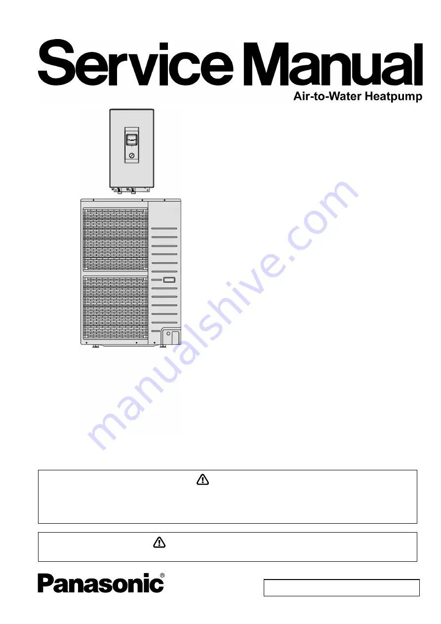
Indoor Unit 

Outdoor Unit


WH-SXH09D0E8 WH-UX09DN8


PRECAUTION OF LOW TEMPERATURE 

In order to avoid frostbite, be assured of no refrigerant leakage during the installation or repairing of refrigerant circuit.


WARNING 

This service information is designed for experienced repair technicians only and is not designed for use by the general public. 
It does not contain warnings or cautions to advise non-technical individuals of potential dangers in attempting to service a product. 
Products powered by electricity should be serviced or repaired only by experienced professional technicians. Any attempt to 
service or repair the product or products dealt with in this service information by anyone else could result in serious injury or death. 

Summary of Contents for WH-SXH09D0E8

Page 1: ...cuit WARNING This service information is designed for experienced repair technicians only and is not designed for use by the general public It does not contain warnings or cautions to advise non technical individuals of potential dangers in attempting to service a product Products powered by electricity should be serviced or repaired only by experienced professional technicians Any attempt to serv...

Page 2: ...ion Control 36 13 1 Protection Control for All Operations 36 13 2 Protection Control for Heating Operation 38 14 Servicing Mode 39 14 1 Test Run 39 14 2 Proper Pump Down Procedure 39 14 3 How to Adjust Water Flow Rate 39 15 Maintenance Guide 40 16 Troubleshooting Guide 42 16 1 Refrigeration Cycle System 42 16 2 Relationship between the Condition of the Air to Water Heatpump Indoor and Outdoor Unit...

Page 3: ...ctrical circuit capacity is not enough or defect found in electrical work it will cause electrical shock or fire 10 This equipment must be properly earthed Earth line must not be connected to gas pipe water pipe earth of lightning rod and telephone Otherwise it may cause electric shock in case equipment breakdown or insulation breakdown 11 Do not use joint cable for indoor outdoor connection cable...

Page 4: ... work The weight of indoor outdoor unit might cause injury if carried by one person 4 Do not touch outdoor unit air inlet and aluminium fin It may cause injury 5 Select an installation location which is easy for maintenance 6 Pb free solder has a higher melting point than standard solder typically the melting point is 50 F 70 F 30 C 40 C higher Please use a high temperature solder iron In case of ...

Page 5: ...t 3 9 8 30 98 4 I D O D Height Difference m ft 20 65 6 Additional Gas Amount g m oz ft 50 0 5 Refrigeration Charge Less m ft 15 49 2 Type Hermetic Motor Motor Type Brushless 4 poles Compressor Rated Output kW 4 30 Type Propeller Fan Material PP Motor Type Induction 8 poles Input Power W Output Power W 60 Fan Fan Speed rpm 490 Top Fan 530 Bottom Fan Fin material Aluminium Pre Coat Fin Type Corrugat...

Page 6: ...t mm inch 28 1 3 32 Water Drain Hose Inner Diameter mm inch 15 00 19 32 Motor Type Capacitor Run Induction Motor 5 μF No of Speed 3 Pump Input Power W 180 Type Brazed Plate No of Plates 80 Size W x H x L mm 130 93 325 Hot Water Coil Water Flow Rate l min m 3 h 25 8 1 5 Pressure Relief Valve Water Circuit kPa Open 190 Close 183 and below Flow Switch Magnetic Lead Switch Protection Device A Residual...

Page 7: ...tart operation Gas leakage protection Prevent compressor reverse cycle Inner protector to protect compressor Serviceability Improvement Breakdown Self Diagnosis function System Status Check Buttons for servicing purpose System Pumpdown Button for servicing purpose Front maintenance design for outdoor unit Operation Condition Indoor Outdoor Water outlet temperature C Ambient temperature C Maximum 5...

Page 8: ...8 4 Location of Controls and Components 4 1 Indoor Unit 4 1 1 Location of Control ...

Page 9: ...9 ...

Page 10: ...10 ...

Page 11: ...11 4 1 2 Weekly Timer Setting ...

Page 12: ...12 4 1 3 Main Components 4 2 Outdoor Unit ...

Page 13: ...13 5 Dimensions 5 1 Indoor Unit ...

Page 14: ...14 5 2 Outdoor Unit ...

Page 15: ...el Gas Liquid Rated Length m Common Length m Max Elevation m Min Piping Length m Max Piping Length m Additional Refrigerant g m UX09DN8 5 8 3 8 7 15 20 3 30 50 If piping length is over common length additional refrigerant should be added as shown in the table ...

Page 16: ...16 7 Block Diagram ...

Page 17: ...17 8 Wiring Connection Diagram 8 1 Indoor Unit ...

Page 18: ...18 8 2 Outdoor Unit ...

Page 19: ...19 9 Electronic Circuit Diagram 9 1 Indoor Unit ...

Page 20: ...20 9 2 Outdoor Unit ...

Page 21: ...21 10 Printed Circuit Board 10 1 Indoor Unit 10 1 1 Main Printed Circuit Board ...

Page 22: ...22 10 2 Outdoor Unit 10 2 1 Main Printed Circuit Board ...

Page 23: ...23 10 2 2 Noise Filter Printed Circuit Board ...

Page 24: ...eration to the system Outdoor Unit If an awning is built over the unit to prevent direct sunlight or rain be careful that heat radiation from the condenser is not obstructed Avoid location where ambient temperature is below 20 C Keep the spaces indicated by arrows from wall ceiling fence or other obstacles Do not place any obstacles which may cause a short circuit of the discharged air If outdoor ...

Page 25: ...stallation plate by moving it left and right 2 Fix the screws to the holes on the hooks of installation plate as illustrated below 11 3 3 2 Water Piping Installation The minimum requirement of water in the system is 30 litres If these values could not be achieved please install additional buffer tank field supply Water inlet and water outlet in indoor unit are used for connection to water circuit ...

Page 26: ...over tightening cause gas leakage 11 3 3 4 Drain Hose Installation Use inner diameter 15 mm drain hose in the market This hose must to be installed in a continuously downward direction and in a frost free environment Do not insert this hose into sewage hose or cleaning hose that may generate ammonia gas sulfuric gas etc If necessary use hose clamp to further tighten the hose at drain hose connecto...

Page 27: ...oor unit before carry out electrical connection The bushing must be used and must not take off 11 3 4 1 Connecting Requirement The equipment s power supply 1 complies with IEC EN 61000 3 2 Terminal screw Tightening torque N cm kgf cm M4 157 196 16 20 M5 196 245 20 25 11 3 4 2 Wire Stripping and Connecting Requirement ...

Page 28: ...ng the flare nut locate at valve onto the copper pipe Align center of piping to valves and then tighten with torque wrench to the specified torque as stated in the table Local pipes can project in any of four directions Make holes in the pipe panels for the pipes to pass through Be sure to install the pipe panels to prevent rain from getting inside the outdoor unit Removing the service panel 1 Rem...

Page 29: ... vacuum pump and from the service port of the 3 way valve 6 Tighten the service port caps of the 3 way valve at a torque of 18 N m with a torque wrench 7 Remove the valve caps of both of the 2 way valve and 3 way valve Position both of the valves to OPEN using a hexagonal wrench 4 mm 8 Mount valve caps onto the 2 way valve and the 3 way valve o Be sure to check for gas leakage CAUTION If gauge nee...

Page 30: ...OOR UNIT section 11 3 4 CONNECT THE CABLE TO THE INDOOR UNIT For three phase model never operate the unit by pressing the electromagnetic switch Never correct the phase by switching over any of the wires inside the unit 11 4 5 Pipe Insulation 1 Please carry out insulation at pipe connection portion as mentioned in Indoor Outdoor Unit Installation Diagram Please wrap the insulated piping end to pre...

Page 31: ...Heating Operation 12 1 1 1 Thermostat control Compressor is OFF when Water Outlet Temperature Internal Water Setting Temperature 2 C for continuously 3 minutes Compressor is ON after waiting for 3 minutes if the Water Outlet Temperature Water Inlet Temperature temperature at thermostat OFF is triggered 3 C 12 1 2 Setting Water Outlet Temperature for Heat Mode The set temperature define the paramet...

Page 32: ...SET Switch pressed for less than 5secs immediately enter water temperature shift setting mode Once enter this setting mode SETTING display is ON This setting mode is used to easily shift the target water outlet temperature 12 1 4 Outdoor Fan Motor Operation Outdoor fan motor is adjusted according to operation condition It starts when compressor starts operation and it stops 30 seconds after compre...

Page 33: ...mp will remain ON when compressor OFF due to thermostat OFF 12 3 Pump Down Operation Purpose Ensure the pump down operation when relocating or disposing of the unit The pump down operation will extract all refrigerant from the piping into the outdoor unit 1 Make sure the OFF ON control panel LED is OFF no operation 2 Press the Pump Down button to start the pump down operation 3 No low pressure pro...

Page 34: ...re not exceeds 80 C the water pump shall be continuously running with normal mode If the water inlet temperature exceeds 80 C for continuously 10 seconds the water pump will be OFF immediately 3 After water pump OFF for more than 10 minutes it will be ON back and the indoor unit safety control checking is restarted 12 6 Auto Restart Control When the power supply is cut off during the operation of ...

Page 35: ... condition 1 When quiet button is presses 2 When quiet request ON time by weekly timer Refer to control panel When any of above mentioned condition is achieved this control is activated During quiet operation operating frequency and outdoor FM rpm will be reduced It will result in capacity loss Cancellation condition 1 Cancel by press quiet button 2 Stop by OFF ON button 3 When quiet request OFF t...

Page 36: ...ses to 95 C compressor will stop immediately 2 Compressor will restart delay 3 minutes when the IPM temperature decreases to 90 C If this condition repeats continuously 4 times within 30 minutes system will stop operation and OFF ON control panel LED will blink F22 error occurs B DC Peak Current Control 1 When the current to IPM exceeds set value of 33 4 5 0 A compressor will stop Compressor will ...

Page 37: ...igger heater START condition o When the outdoor air temperature is 4 C or below and discharge temperature is 11 6 C or below b Resetting heater STOP condition 1 When the outdoor air temperature above 6 C 2 When the discharge temperature above 18 9 C 13 1 9 Low Pressure Protection Control Purpose To protect the system operation Detection period After compressor on for 5 minutes Detection conditions...

Page 38: ...s activated 5Hz up every 30 sec until it reaches the target frequency Cancellation condition starting condition not fulfill Cancel the extreme low temperature control when compressor discharge sensor 60 C 13 2 Protection Control for Heating Operation 13 2 1 Outdoor Air Temperature Control The maximum current value is regulated when the outdoor air temperature rises above 14 C in order to avoid com...

Page 39: ...DW switch on control panel to begin PUMP DOWN mode Operate the system in PUMP DOWN mode for 10 15 minutes 3 After 10 15 minutes after 1 or 2 minutes in case very low ambient temperatures 10 C fully close 3 way valve Liquid Side 4 After 3 minutes fully close 3 way valve Gas Side 5 Press the OFF ON switch on control panel to stop PUMP DOWN mode 6 Remove the refrigerant piping 14 3 How to Adjust Wate...

Page 40: ...nish o In case the water keeps drained out from the unit switch off the system and then contact your local authorized dealer 3 Indoor unit control board area Thorough visual inspection of the control board and look for defects i e loose connection melting of wire insulator and etc 4 RCCB Ensure the RCCB set to ON condition before check RCCB Turn on the power supply to the indoor unit This testing ...

Page 41: ...r of indoor unit indicated with WATER IN Refer to figure below o Use spanner to detach the tube connector nut o Take out the filter carefully so that not deforms it shape o Use tap water only to wash the residue on the filter If necessary gently use soft brush only to clean the hard dirt o After clean put it back to the original location and tighten the nut connection with torque wrench ...

Page 42: ...no electrical problems before inspecting the refrigeration cycle Such problems include insufficient insulation problem with the power source malfunction of a compressor and a fan The normal pressure of the refrigeration cycle depends on various conditions the standard values for them are shown in the table on the right ...

Page 43: ...nits Low Pressure High Pressure Electric current during operation Water leakage or insufficient water flow rate in the system Excessive amount of refrigerant Inefficient compression Insufficient refrigerant gas leakage Outdoor heat exchange deficiency Clogged expansion valve or Strainer Carry out the measurements of pressure electric current and temperature fifteen minutes after an operation is st...

Page 44: ...IC memory To check the error code 1 When an abnormality occurs system will stop operation and OFF ON control panel LED will blink 2 Error code of the abnormality will display on the control panel timer display LCD 3 To determine the abnormality description the error code table needs to be referred To display past last error code 1 Turn ON power supply 2 Press and hold the CHECK button for more tha...

Page 45: ...20 minutes Outdoor compressor F15 Outdoor fan motor lock abnormality 2 times occurrence within 30 minutes Outdoor PCB Outdoor fan motor F16 Total running current protection 3 times occurrence within 20 minutes Excess refrigerant Outdoor PCB F20 Outdoor compressor overheating protection 4 times occurrence within 30 minutes Compressor tank temperature sensor Clogged expansion valve or strainer Insuf...

Page 46: ...circuit Insufficient refrigerant Outdoor PCB Compressor low F48 Outdoor EVA outlet temperature sensor abnormality Continue for 5 sec Outdoor EVA outlet temperature sensor defective or disconnected F49 Outdoor bypass outlet temperature sensor abnormality Continue for 5 sec Outdoor bypass outlet temperature sensor defective or disconnected ...

Page 47: ...ration of cooling and heating the capability rank of indoor checked by the outdoor is used to determine connection capability rank abnormality Malfunction Caused 1 Wrong model interconnected 2 Wrong indoor unit or outdoor unit PCB main used 3 Faulty indoor unit or outdoor unit PCB main Abnormality Judgment Continue for 90 seconds ...

Page 48: ...During startup and operation of cooling and heating the temperatures detected by the compressor tank temperature sensor are used to determine sensor error Malfunction Caused 1 Faulty connector connection 2 Faulty sensor 3 Faulty outdoor unit PCB main Abnormality Judgment Continue for 5 seconds ...

Page 49: ... During startup and operation of cooling and heating the temperatures detected by the indoor refrigerant liquid temperature sensor are used to determine sensor error Malfunction Caused 1 Faulty connector connection 2 Faulty sensor 3 Faulty indoor unit PCB main Abnormality Judgment Continue for 5 seconds ...

Page 50: ...ove 26 C is detected by the outdoor pipe temperature sensor Malfunction Caused 1 Dust accumulation on the outdoor unit heat exchanger 2 Air short circuit at outdoor unit 3 2 way valve partially closed 4 Faulty outdoor unit fan motor 5 Refrigerant shortage refrigerant leakage 6 Clogged expansion valve or strainer 7 Faulty outdoor pipe temperature sensor 8 Faulty outdoor unit main PCB main ...

Page 51: ...etected by the indoor water flow switch is used to determine water flow error Malfunction Caused 1 Faulty water pump 2 Water leak in system 3 Faulty connector connection 4 Faulty water flow switch 5 Faulty indoor unit PCB main Abnormality Judgment Continue for 10 seconds but no judgment for 9 minutes after compressor startup restart ...

Page 52: ...n Conditions During operation of cooling and heating when the outdoor high pressure sensor output signal is 0Vdc or 5Vdc Malfunction Caused 1 Faulty connector connection 2 Faulty sensor 3 Faulty outdoor unit PCB main Abnormality Judgment Continue 4 times in 20 minutes ...

Page 53: ...ation Abnormality H76 Malfunction Decision Conditions During standby and operation of cooling and heating indoor control panel error occur Malfunction Caused 1 Faulty connector connection 2 Faulty control panel 3 Faulty indoor unit PCB main ...

Page 54: ...s normal Malfunction Caused 1 Faulty outdoor unit PCB main 2 Faulty indoor unit PCB main 3 Indoor outdoor signal transmission error due to wrong wiring 4 Indoor outdoor signal transmission error due to breaking of wire in the connection wires between the indoor and outdoor units 5 Indoor outdoor signal transmission error due to disturbed power supply waveform Abnormality Judgment Continue for 1 mi...

Page 55: ...ween Indoor and Outdoor H95 Malfunction Decision Conditions The supply power is detected for its requirement by the indoor outdoor transmission Malfunction Caused 1 Insufficient power supply 2 Faulty outdoor unit PCB noise filter main ...

Page 56: ...ssure 4 0MPa and above is detected by outdoor high pressure sensor Malfunction Caused 1 Faulty water pump 2 Insufficient water flow rate in system 3 Water leak in system 4 2 3 way closed 5 Clogged expansion valve or strainer 6 Excessive refrigerant 7 Faulty outdoor high pressure sensor 8 Faulty outdoor unit PCB main ...

Page 57: ...door refrigerant liquid temperature 0 C Malfunction Caused 1 Faulty water pump 2 Insufficient water flow rate in system 3 Water leak in system 4 2 way valve partially closed 5 Clogged expansion valve or strainer 6 Refrigerant shortage refrigerant leakage 7 Faulty indoor refrigerant liquid temperature sensor 8 Faulty indoor unit PCB main ...

Page 58: ...lfunction Caused 1 Dust accumulation on the outdoor unit heat exchanger 2 Air short circuit at outdoor unit 3 Faulty water pump 4 Insufficient water flow rate in system 5 Water leak in system 6 2 3 way valve closed 7 Clogged expansion valve or strainer 8 Excessive refrigerant 9 Faulty outdoor high pressure sensor and switch 10 Faulty outdoor unit PCB Abnormality Judgment Continue 4 times in 20 min...

Page 59: ...compressor rotation failure is detected by checking the compressor running condition through the position detection circuit Malfunction Caused 1 Compressor terminal disconnect 2 Faulty outdoor unit PCB main 3 Faulty compressor Abnormality Judgment Continue 4 times in 20 minutes ...

Page 60: ... fan motor feedback of rotation 2550rpm or 50rpm Malfunction Caused 1 Operation stop due to short circuit inside the fan motor winding 2 Operation stop due to breaking of wire inside the fan motor 3 Operation stop due to breaking of fan motor lead wires 4 Operation stop due to fan motor Hall IC malfunction 5 Operation error due to faulty outdoor unit PCB Abnormality Judgment Continue 2 times in 20...

Page 61: ...itions During operation of cooling and heating when outdoor current above 10 6A is detected by the current transformer CT in the outdoor unit PCB Malfunction Caused 1 Excessive refrigerant 2 Faulty outdoor unit PCB main Abnormality Judgment Continue 3 times in 20 minutes ...

Page 62: ...ve 112 C is detected by the compressor tank temperature sensor Malfunction Caused 1 Faulty compressor tank temperature sensor 2 2 3 way valve closed 3 Refrigerant shortage refrigerant leakage 4 Clogged expansion valve or strainer 5 Faulty outdoor unit PCB main 6 Faulty compressor Abnormality Judgment Continue 4 times in 20 minutes ...

Page 63: ...onditions During operation of cooling and heating when temperature 95 C is detected by the outdoor IPM temperature sensor Malfunction Caused 1 Faulty outdoor unit fan motor 2 Faulty outdoor unit PCB main Abnormality Judgment Continue 4 times in 30 minutes ...

Page 64: ...ns During operation of cooling and heating when outdoor DC current is above 33 4 5 0A is detected by the IPM DC Peak sensing circuitry in the outdoor unit PCB main Malfunction Caused 1 Faulty outdoor unit PCB main 2 Faulty compressor Abnormality Judgment Continue for 7 times ...

Page 65: ...et temperature indoor refrigerant liquid temperature 5 C 4 During operation of heating indoor refrigerant liquid temperature water inlet temperature 5 C Malfunction Caused 1 Faulty water inlet or indoor refrigerant liquid temperature sensors 2 2 3 way valve closed 3 Refrigerant shortage refrigerant leakage 4 Clogged expansion valve or strainer 5 Faulty outdoor unit PCB main 6 Poor compression of c...

Page 66: ...temperature of thermostat ON indoor unit 0 C 2 During cooling operation when the indoor pipe temperature of thermostat ON indoor unit 45 C Malfunction Caused 1 Faulty sensor 2 Faulty connector connection 3 Faulty outdoor unit PCB noise filter main 4 Faulty four way valve Abnormality Judgment Continue 4 times in 30 minutes ...

Page 67: ...l F27 Malfunction Decision Conditions During compressor stop and outdoor high pressure switch is remain opened Malfunction Caused 1 Faulty connector connection 2 Faulty switch 3 Faulty outdoor unit PCB main Abnormality Judgment Continue for 1 minute ...

Page 68: ... During startup and operation of cooling and heating the temperatures detected by the outdoor air temperature sensor are used to determine sensor error Malfunction Caused 1 Faulty connector connection 2 Faulty sensor 3 Faulty outdoor unit PCB main Abnormality Judgment Continue for 5 seconds ...

Page 69: ... During startup and operation of cooling and heating the temperatures detected by the indoor water inlet temperature sensor are used to determine sensor error Malfunction Caused 1 Faulty connector connection 2 Faulty sensor 3 Faulty indoor unit PCB main Abnormality Judgment Continue for 5 seconds ...

Page 70: ... During startup and operation of cooling and heating the temperatures detected by the outdoor discharge pipe temperature sensor are used to determine sensor error Malfunction Caused 1 Faulty connector connection 2 Faulty sensor 3 Faulty outdoor unit PCB main Abnormality Judgment Continue for 5 seconds ...

Page 71: ...ng operation of cooling and heating when the PFC protection circuitry in the outdoor unit PCB main senses abnormal high DC voltage level Malfunction Caused 1 Power supply surge 2 Compressor windings not uniform 3 Faulty outdoor unit PCB main Abnormality Judgment Continue 4 times in 20 minutes ...

Page 72: ... During startup and operation of cooling and heating the temperatures detected by the outdoor pipe temperature sensor are used to determine sensor error Malfunction Caused 1 Faulty connector connection 2 Faulty sensor 3 Faulty outdoor unit PCB main Abnormality Judgment Continue for 5 seconds ...

Page 73: ... During startup and operation of cooling and heating the temperatures detected by the outdoor defrost temperature sensor are used to determine sensor error Malfunction Caused 1 Faulty connector connection 2 Faulty sensor 3 Faulty outdoor unit PCB main Abnormality Judgment Continue for 5 seconds ...

Page 74: ... During startup and operation of cooling and heating the temperatures detected by the indoor water outlet temperature sensor are used to determine sensor errors Malfunction Caused 1 Faulty connector connection 2 Faulty sensor 3 Faulty indoor unit PCB main Abnormality Judgment Continue for 5 seconds ...

Page 75: ...mer CT open circuit is detected by checking the compressor running frequency rated frequency and CT detected input current 0 65A for continuously 20 seconds Malfunction Caused 1 CT defective 2 Faulty outdoor unit PCB 3 Compressor defective low compression Abnormality Judgment Continue 3 times in 20 minutes ...

Page 76: ...w for take out front plate Before removing the front plate of indoor unit always switch off all power supply i e indoor unit power supply heater power supply and boiler tank power supply 1 Remove the 2 mounting screws which located at bottom of the front plate and 1 mounting screw at the front of the plate 2 Gently pull the lower section of the front plate towards you to remove the front plate fro...

Page 77: ...77 17 3 To Remove Pressure Gauge 17 4 To Remove Control Panel ...

Page 78: ...78 17 5 To Remove RCCB 17 6 To Remove Transformer and Electronic Controller Board ...

Page 79: ...79 17 7 To Remove Pressure Relief Valve Flow Switch Water Pump and Bottle Complete When reinstall the water pipe use grease or water at the joining ...

Page 80: ...80 When reinstall the water pipe use grease or water at the joining ...

Page 81: ... C WBT Indoor water inlet temperature 30 C Indoor water outlet temperature 35 C Piping length 7m 8 000 9 000 10 000 11 000 12 000 13 000 14 000 15 13 11 9 7 5 3 1 1 3 5 7 9 11 13 15 17 19 21 23 25 Outdoor Air Temperature C Capacity kW 1 700 2 200 2 700 3 200 3 700 15 13 11 9 7 5 3 1 1 3 5 7 9 11 13 15 17 19 21 23 25 Outdoor Air Temperature C Input Power kW ...

Page 82: ...7 C DBT 6 C WBT Indoor water inlet temperature 30 C Indoor water outlet temperature 35 C 1 800 1 850 1 900 1 950 2 000 2 4 6 8 10 12 14 16 18 20 22 24 26 28 30 Piping Length m Input Power kW 7 200 7 700 8 200 8 700 9 200 2 4 6 8 10 12 14 16 18 20 22 24 26 28 30 Piping Length m Capacity kW ...

Page 83: ...20 9 00 3 66 9 00 4 11 9 00 4 31 9 00 4 50 2 9 00 2 40 9 00 2 55 9 00 2 82 9 00 3 09 9 00 3 60 9 00 4 11 7 9 00 1 68 9 00 1 90 9 00 2 20 9 00 2 50 9 00 2 80 9 00 3 10 25 13 60 1 54 13 60 1 75 13 20 1 97 12 80 2 18 12 00 2 45 11 20 2 71 HC Heating Capacity kW IP Power Input kW LWC Leaving Water Condenser Temperature C Tamb Ambient Temperature C 18 3 Hydraulic Pump Performance ...

Page 84: ...9 Exploded View and Replacement Parts List 19 1 Indoor Unit Note The above exploded view is for the purpose of parts disassembly and replacement The non numbered parts are not kept as standard service parts ...

Page 85: ...RMINAL BOARD ASS Y 1 CWA28K1240 29 RESIDUAL CURRENT CIRCUIT BREAKER 1 CWA181008 O 30 TRANSFORMER COMPLETE 1 CWA40C1075 O 31 SENSOR COMPLETE 1 CWA50C2762 O 32 REMOTE CONTROL COMPLETE 1 CWA75C3699 O 33 PRESSURE GAUGE 1 CWB070001 O 34 PRESSURE RELIEF VALVE 1 CWB621011 O 35 CABINET 1 CWE001050A 36 HANDLE 2 CWE161008 37 CABINET FRONT PLATE 1 CWE061265A 38 INSTALLING HOLDER 1 CWH361103A 39 OPERATING INS...

Page 86: ...86 19 2 Outdoor Unit ...

Page 87: ...87 ...

Page 88: ...88 Note The above exploded view is for the purpose of parts disassembly and replacement The non numbered parts are not kept as standard service parts ...

Page 89: ... COMP DEF 1 CWA50C2577 28 CABINET REAR PLATE 1 CWE02C1064 29 CONTROL BOARD CASING 1 CWH10K1049 31 TERMINAL BOARD ASS Y 1 CWA28K1214 38 ELECTRONIC CONTROLLER NOISE FILTER 1 CWA745822 O 44 ELECTRONIC CONTROLLER MAIN 1 CWA73C5784R O 46 REACTOR 3 G0C293J00001 48 TERMINAL COVER 1 CWH171039A 49 NUT FOR TERMINAL COVER 1 CWH7080300J 50 BRACKET FAN MOTOR 1 CWD54K1024 50a SCREW BRACKET FAN MOTOR 2 CWH551040...

Page 90: ...ELECTRO MAGNETIC SWITCH 1 K6C2AGA00002 78 ELECTRO MAGNETIC SWITCH 1 K6C4E8A00001 79 REACTOR 3 G0C153J00009 80 PTC THERMISTORS 1 D4DDG1010001 81 CAPACITOR FM 3 DS441205NPQA Note All parts are supplied from PHAAM Malaysia Vendor Code 00029488 O marked parts are recommended to be kept in stock PHAAM Printed in Malaysia FY1108 0 ...

Reviews: