


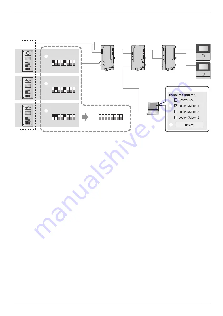
Example of an extension box connected to port 1 of the control box ([Lobby Station 1] must be selected in
the Setup tool)
The following procedure is an example of how to configure settings for the system shown in the following illustration.
Extension box
(
Up to
3)
Lobby station
(Up to 18: 6 lobby stations per extension box with max. of 3 extension boxes)
PC
Distribution box
Main monitor
Control box (1)
PC setup tool
2
3
DIP switch
DIP switch
1 2 3 4 5 6 7 8
ON
OFF
1 2 3 4 5 6 7 8
ON
OFF
1 2 3 4 5 6 7 8
ON
OFF
6
1 2 3 4 5 6 7 8
ON
OFF
1
1st lobby station 1
4
2nd lobby station 1
5
3rd lobby station 1
Lobby station
1 group
(off)
Important:
R
Settings for each lobby station connected to an extension box must be configured separately.
R
DIP switches on the extension box are used to determine which lobby station that settings are uploaded
to. The number 6 - 8 switches must always be set to the "off" position. (For a list of DIP switch settings,
see page 56.)
1. DIP switch setting of extension box:
Set the DIP switches to the settings shown under "
A
1st lobby station 1".
2. PC setup tool: Load and edit the data
Start the setup tool. In the
[Load and edit the data]
section, configure the required
[Room settings]
and
[General
settings]
for
[Lobby Station 1]
.
3. PC setup tool: Upload the data to device
In the
[Upload the data to device]
section, select
[Lobby Station 1]
as shown next to "
B
" under "PC setup
tool", and then click
[Upload]
as shown next to "
C
" under "PC setup tool".
4. DIP switch setting of extension box:
Set the DIP switches to the settings shown under "
D
2nd lobby station 1".
5. PC setup tool: Upload the data to device
6. DIP switch setting of extension box:
Set the DIP switches to the settings shown under "
E
3rd lobby station 1".
7. PC setup tool: Upload the data to device
8. DIP switch setting of extension box:
After configuring all the lobby stations, set all the DIP switches of the extension box to the "off" position as shown
under "
F
".
55
5. Programming


