background image

6

7

Quick Start Guide

AV4

S-V

V

L

R

TV

N

F.P.

MULTI

WINDOW

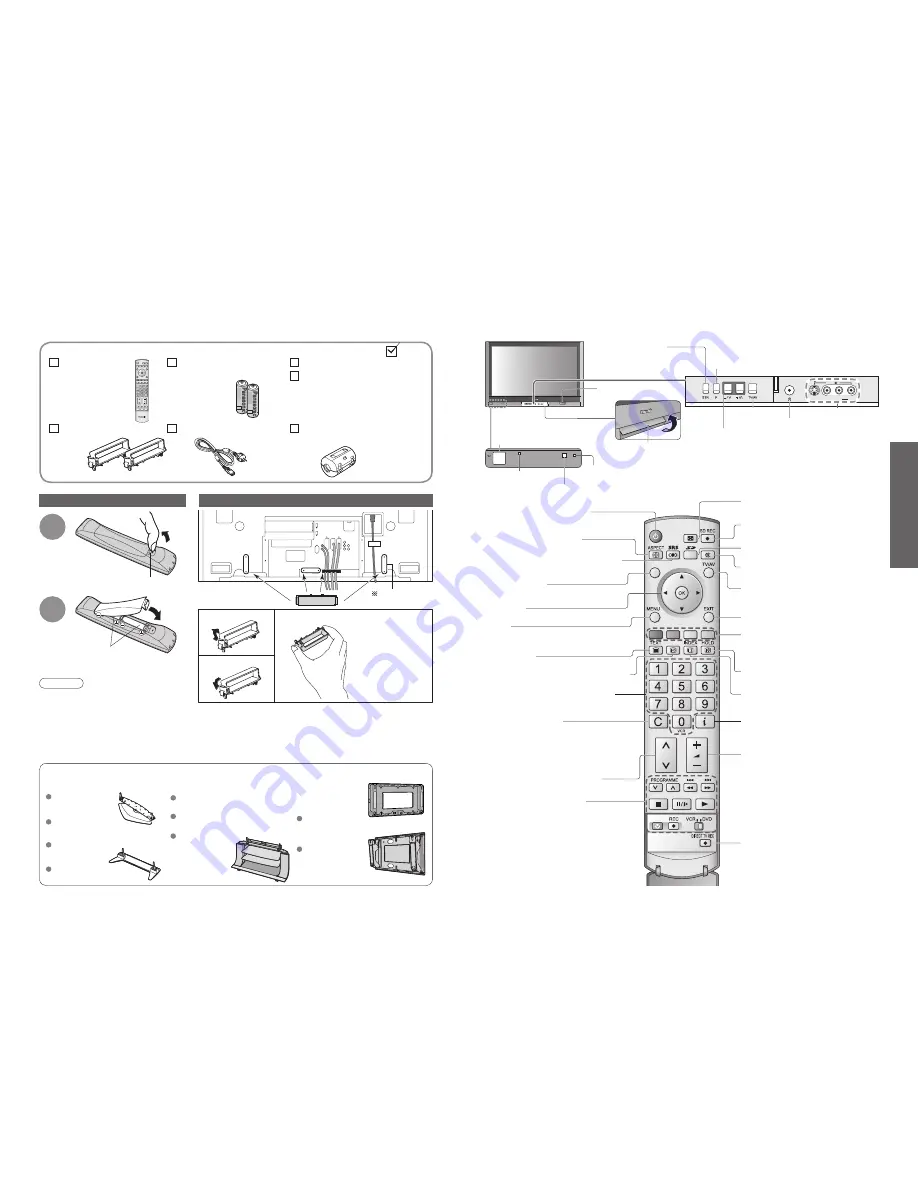
Installing remote's batteries


Batteries for the Remote

Control Transmitter 

(2)

• 

R6 (UM3)

Identifying Controls

Accessories / Options


Clamper 

(2)


Mains Lead

1

Pull 

open

Hook

2

Note the correct

polarity (+ or -)

Close

Snap open

Snap shut

Caution

• 

Incorrect installation may cause battery 

leakage and corrosion, resulting in 

damage to the remote control unit.

• 

Do not mix old and new batteries.

• 

Do not mix different battery types (such as 

alkaline and manganese batteries).

• 

Do not use rechargeable (Ni-Cd) batteries.

• 

Do not burn or breakup batteries.


Remote Control 

Transmitter

• 

N2QAYB000025


Operating Instructions


Pan European Guarantee Card

Attaching the cable clampers

• 

Do not bundle the RF cable and mains lead together (could cause 

distorted image).

• 

Fix cables with clampers as necessary.

• 

When using the optional accessory, follow the option’s assembly 

manual to 

fi

 x cables.

Function 

select

Increases or decreases the programme position by 

one. When a function is already displayed, press to 

increase or decrease the selected function.

When in Standby mode, switches TV On.

On / Off switch

Swing up the door at "PULL".

C.A.T.S. (Contrast Automatic Tracking System) sensor

(senses brightness to adjust picture quality in "Auto" viewing mode) (p. 16)

Power lamp

(standby: red)

Remote control 

signal receiver

Switches TV/AV

  Volume / Contrast / Brightness / Colour / Sharpness 

/ Tint (NTSC mode) / Bass / Treble / Balance / 
Tuning mode (p. 20)

Standard accessories

• 

Identifying Controls

• 

Accessories / Options

Check that you have the accessories and items shown

Remove from the TV unit

Push both side 

hooks and pull out

(

)

Headphones jack (p. 30)

AV4 terminals (p. 30)


Ferrite core 

• 

J0KF00000018

Store setting

 (p. 20)

Used to store tuning and 

other function settings

(

)

Optional accessories

Pedestal

Plasma TV stand

Wall-hanging

bracket

(vertical)

TY-WK42PV3W

(angle)

TY-WK42PR3W

TY-ST42P600W

TY-S37PX600W

(TH-37PV600E)

TY-S42PX600W

(TH-42PV600E)

(TH-37PV600E, 

TH-42PV600E)

TY-ST42P60W

(TH-37PV600E,

TH-42PV600E)

TY-ST50P60W

(TH-50PV600E)

TY-S50PX600W

(TH-50PV600E)

SD CARD slot (p. 22)

TY-ST50P600W

(TH-50PV600E)

Rear of the TV

Switches TV to On or Standby

(On / Off switch in On position)

Sound mute On / Off

Changes aspect ratio

 (p. 11)

Normalizes

 (p. 16)

(Resets settings)

Selects programmes in sequence

Viewing a favourite teletext channel 

(p. 14)

Teletext 

(p. 14)

Select / OK

VCR / DVD operations 

(p. 13)

Volume

Programme Information 

(p. 11)

Teletext Index 

(p. 14)

Still Picture 

(p. 11)

Coloured buttons

(used for various functions)
(for example, see p. 14)

EXIT 

(Returns to TV screen)

Switches TV/AV

(To watch videos or DVDs) (p. 12)

DIRECT TV Recording


To immediately record programme 

in VCR / DVD recorder with Q-Link 

connection

(p. 26)

(

)

MENU

  Press to access the Picture, Sound and 

Setup menus

(

)

Direct channel access 

  During normal TV viewing or when in the 

Tuning, Programme edit or Manual tuning 

menus, press and then enter channel number 

using the numeric buttons

  Press twice to change to the Cableband mode

(

)

SD menu 

(p. 22 and 24)

SD Recording 

(p. 24)

MULTI WINDOW 

(p. 11)

Switches SRS TruSurround XT On / Off


(p. 17)

Changes programme / channel 

(p. 10)


TH-37PV600E has 

horizontal direction.

Summary of Contents for Viera TH-37PV600E

Page 1: ...ase contact your dealer or supplier for further information Information on Disposal in other Countries outside the European Union This symbol is only valid in the European Union If you wish to discard this product please contact your local authorities or dealer and ask for the correct method of disposal Printed in Czech Republic Licence Trademark Credits VGA is a trademark of International Busines...

Page 2: ...nced Features How to Use Menu Functions 16 picture sound quality etc Editing and Setting Channels 18 Displaying PC Screen on TV 21 Watching SD Card Videos and photos 22 Recording a Programme on SD Card 24 External Equipment 26 Q Link Control with HDMI Connections Basic Features Watching TV 10 Watching Videos and DVDs 12 Viewing Teletext 14 Enjoy your TV Technical Information 32 FAQs 36 SD Card On ...

Page 3: ... not move the TV with the lead plugged in the socket outlet Do not place a heavy object on the lead or place the lead near a high temperature object Do not twist the lead bend it excessively or stretch it Do not pull on the lead Hold onto the mains plug body when disconnecting lead Do not use a damaged mains plug or socket outlet Electronic equipment In particular do not place video equipment near...

Page 4: ... accessories Identifying Controls Accessories Options Check that you have the accessories and items shown Remove from the TV unit Push both side hooks and pull out Headphones jack p 30 AV4 terminals p 30 Ferrite core J0KF00000018 Store setting p 20 Used to store tuning and other function settings Optional accessories Pedestal Plasma TV stand Wall hanging bracket vertical TY WK42PV3W angle TY WK42P...

Page 5: ...ally These steps are not necessary if the setup has been completed your local dealer VHF UHF aerial Rear terminal portion enlarged view Rear of the TV Mains lead Fastener To unfasten Connect to AV2 or AV3 for a unit supporting Q Link p 26 Watching TV To record TV programmes Auto Setup is now complete and your TV is ready for viewing You can now use the remote control to turn On the unit or turn th...

Page 6: ...tio or Each press changes the mode Change the aspect ratio p 32 While the bar is displayed red green Auto aspect 16 9 14 9 Just 4 3 4 3 Full HD signal only Zoom1 Zoom2 Zoom3 in a short time 1 View in multi window p 35 Watch TV DVD etc in multi window Main screen Colour bar Sub screen Remote control operations apply to the main screen To change the layout etc first show the colour bar MULTI WINDOW ...

Page 7: ...connect the equipment p 30 Select the connector connected to the equipment AV mode screen Note Automatic Input selection Input mode is automatically switched from TV to AV mode when the equipment connected via SCART or HDMI terminal is operated When the equipment is turned off the TV is set to TV mode If the external equipment has an aspect adjustment function set to 16 9 For details see the manua...

Page 8: ...ist mode four differently coloured page numbers are situated at the bottom of the screen Each of these numbers can be altered and stored in the TV s memory Store frequently viewed pages p 15 To change mode Teletext in Setup menu p 16 To adjust contrast As the blue bar is displayed FULL TOP BOTTOM Reveal hidden data Re hide red Reveal hidden words e g quiz page answers Using teletext conveniently T...

Page 9: ...ural Mono Stereo Normally Stereo Stereo signal cannot be received Mono M1 M2 Available while mono signal is transmitted MPX Stereo Mode Improves sound quality for music and dramas Music Speech Mode Music SRS TruSurround XT SRS TruSurround XT creates a realistic 5 1 surround sound experience from any two channel source material using just two speakers Off On Switching is also possible by SRS button...

Page 10: ...the Name field Select the character To next character Repeat Select the programme number to edit Programme number Name Edit Programme edit Prog Chan Name Lock Sys 1 2 3 4 5 CH44 CH51 CH41 CH47 CH37 ABC XYZ FTP 123 456 Off Off Off Off Off SC1 SC1 SC1 SC1 SC1 To lock Select the Lock field Select On Off to unlock You cannot select the channel with number buttons or the C button when locked Store Edit...

Page 11: ...k adjustment Set to the minimum level if noise occurs Sync Chooses another synchronous signal if the image is distorted H V On G H V by the horizontal and vertical signals from your PC On G by the green signal from your PC if available Volume correction Side panel Power save OSD language p 16 Sound menu p 16 Displaying PC Screen on TV Editing and Setting Channels Set automatically Auto setup Set m...

Page 12: ...Operation guide Thumbnail screen Caution During the playback no signals are output from the monitor output terminals Date shows the date on which the recording was made by this unit DIGA or D snap Its format is 01 01 2000 when recordings are made without date signal To return to TV To return to the SD menu Videos Photos To change the aspect ratio SD Card next select select set Label surface Videos...

Page 13: ...n the SD card During recording it is possible to watch other terminals input signal Recordable time is displayed if the recording time is not set p 25 Start recording Cancel Set Select the SD mode Select Setup Start recording Not enough memory Current setting Rec time 180min Rec mode Economy Recordable at 15min Card capacity is not enough Continue Recording is stopped when the card capacity is ful...

Page 14: ...sonic equipments Panasonic DVD Recorder DIGA Panasonic Player theatre Panasonic Amplifier etc allow you to enjoy the easy playback or home theatre About connections see Connections p 29 Read the manuals of the equipment too Non HDMI compliant cables cannot be utilized About applicable equipments consult your local Panasonic dealer next select select Easy playback Automatic Input switching When the...

Page 15: ...nect DVD player Playback Connect Set top box RGB input Connect VCR DVD recorder and Set top box example Connect DVD recorder and VCR example Easy playback For connection to HDMI2 terminal refer to p 30 Rear of the TV Rear of the TV Front of the TV Rear of the TV Front of the TV Rear of the TV Rear of the TV Rear of the TV This TV Panasonic Player theatre Panasonic DVD recorder DIGA Panasonic Ampli...

Page 16: ...h equipment the table below and the specifications p 39 AUDIO Computer Amplifier with speaker system Set top box DVD Recorder VCR SCART cable RF cable or Q Link Recommended Connection SCART cable PC Listening Q Link Control with HDMI p 27 To watch satellite broadcasts To record playback To watch DVDs Types of connectable equipment to each connector DVD player Connections overview To listen with sp...

Page 17: ...PC connection A PC may be connected to this TV unit so that the PC screen is displayed and sound is heard from the TV PC signals that can be inputted Horizontal scanning frequency 31 to 69 kHz vertical scanning frequency 59 to 86 Hz more than 1 024 signal lines could result in incorrect display of the image A PC adapter is not necessary for the DOS V compliant D sub 15 pin connector Note Some PC m...

Page 18: ...arbitrary characters Usable characters 1 byte a to f A to F and 0 to 9 Created automatically PRL 3 digit arbitrary characters You can watch two images at once such as a TV programme and a DVD p 11 The TV unit has one tuner Two programmes cannot be displayed at once You cannot make Sub screen source same as Main screen This function cannot be used with a PC HDMI SD card or when progressive signals ...

Page 19: ...noisy Set P NR in the Picture menu to remove noise p 16 Check nearby electrical products car motorcycle fluorescent lamp No image can be displayed Is Colour or Contrast in the Picture menu set to the minimum p 16 Blurry or distorted image no sound or low volume Reset channels p 20 Neither image nor sound is produced Is the unit in AV mode Is the mains lead plugged into the socket outlet Is the TV ...

Page 20: ...rt 95 mm 1 077 mm 689 mm 138 panel part 95 mm 1 266 mm 802 mm 138 panel part 95 mm Weight 28 5 k Net 32 5 k Net 43 0 k Net 38 39 SD Card On screen messages Message Meaning Action Specifications Note Design and Specifications are subject to change without notice Weight and Dimensions shown are approximate This equipment complies with the EMC standards listed below EN55013 EN61000 3 2 EN61000 3 3 EN...

Reviews: