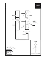
11 Voltage Chart of Connectors on Main P.C.B.
MODE
REC
PIN NO.
MODE
REC
PIN NO.
MODE
REC
PIN NO.
MODE
REC
PIN NO.
MODE
REC
PIN NO.
MODE
REC
PIN NO.
MODE
REC
PIN NO.
B21
1
2.9
2
0
3
0.6
4
2.2
5
0.6
6
0.6
7
2.0
8
0.9
9
1.0
10
2.0
11
0
12
3.3
13
0
14
3.3
15
3.3
16
0
17
3.3
18
4.8
19
4.8
20
4.8
21
0
22
0
23
0
24
0
25
0
26
0
27
0
28
0
29
0
30
0
31
1.2
32
1.2
33
3.3
34
3.3
35
3.3
36
3.3
37
3.3
38
0
39
0
40
0
41
4.5
42
4.5
43
4.5
44
0
45
3.3
46
0
47
3.3
48
0
49
0
50
0.5
51
0.5
52
0.5
53
0.5
54
1.0
55
0.5
56
0.5
57
0
58
0
59
2.9
60
0
B51
1
---
2
0
3
---
4
---
5
0
6
3.2
7
0
8
0
9
0
10
0
11
0
12
2.8
13
0
14
0
15
0
16
3.3
17
3.3
18
3.3
19
0
20
0
21
3.3
22
3.3
23
3.3
24
3.3
25
3.3
26
0
27
0
28
0
29
0.7
30
0.7
31
0
32
0.1
33
0
34
0.1
35
0
36
0
37
---
38
---
39
0
40
---
FP11
1
8.0
2
8.0
3
8.0
4
8.0
5
8.0
6
8.0
7
---
8
2.9
9
2.9
10
---
11
0
12
0
13
0
14
0
15
0
16
0
FP31
1
8.3
2
0
3
-0.2
4
-0.2
5
-6.0
6
-6.0
7
0
8
0
9
12.0
10
6.1
11
-6.4
12
1.3
13
1.7
14
6.6
FP41
1
4.8
2
2.5
3
0.4
4
1.1
5
0
6
0
7
1.4
8
1.5
9
0
10
2.6
11
0
12
0
13
1.5
14
0
15
1.5
16
4.8
FP61
1
2.8
2
---
3
0
4
---
5
2.9
6
---
7
0
8
---
9
0
10
---
11
2.9
12
2.9
13
---
14
0
15
---
16
1.7
17
---
18
2.8
19
---
20
1.5
21
---
22
0
23
---
24
2.9
FP71
1
1.5
2
1.5
3
1.5
4
1.5
5
4.2
6
4.8
7
0
8
4.8
9
0
10
4.1
11
1.3
12
0
13
1.5
14
1.5
15
1.5
16
1.5
17
0.5
18
0
19
2.0
20
1.5
21
0.9
22
1.5
FP72
1
1.5
2
1.4
3
1.4
4
1.5
5
1.1
6
1.5
7
1.9
8
1.5
9
1.9
10
1.5
11
1.1
12
1.5
FP81
1
0.9
2
0.5
3
2.8
4
2.9
5
---
6
0
7
2.9
8
0
9
0
10
0
11
1.4
12
4.8
13
4.8
14
2.3
15
0
16
1.2
17
2.2
18
2.9
19
0
20
2.6
21
2.6
22
2.6
23
2.6
24
0
25
0
26
2.9
27
8.6
28
0
29
1.4
30
1.4
31
0
32
0
FP91
1
2.9
2
0
3
0
4
0
5
0
6
2.6
7
-0.7
8
2.6
9
8.6
10
2.6
11
0.2
12
2.6
13
2.2
14
0
15
1.3
16
1.4
17
1.4
18
2.3
MAIN P.C.B.
49
Summary of Contents for VDR-D220E
Page 8: ...4 Specifications 8 ...
Page 11: ...6 Service Fixture Tools 6 1 Service Fixture and Tools 11 ...
Page 13: ...Fig 3 13 ...
Page 39: ...39 ...
Page 50: ...50 ...
Page 52: ...52 ...