background image

29

Operation

Touch Panel Setup

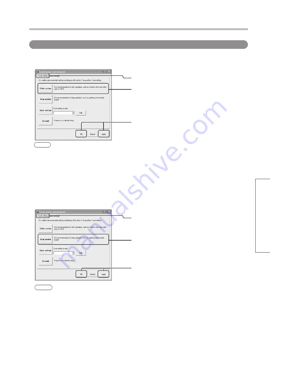
  Start up the setup panel (p. 20).

  Click on the “Touch setting” tab. 

 Click on the “Click action” button.

  Click on the “OK” or “Apply” button.

  Start up the setup panel (p. 20).

  Click on the “Touch setting” tab.

  Click on the “Drag action” button.

  Click on the “OK” or “Apply” button.

Touch setting

 Click action

This setting enables easy clicking operations on the touch panel.

 Drag action

This setting enables dragging operations when the touch panel is used to draw pictures or as  

an electronic blackboard.

Note

The Click action button sets double-clicking range and time slightly longer than ordinary clicking and 

differentiates slight movements at the touch position from dragging so that clicking is accurately done by 

touching. 

For this reason, some follow is sacrificed.

Note

The Drag action button emphasizes follow so that smooth lines can be drawn on the touch panel. However, 

double-clicking and clicking operations may become more difficult.

Summary of Contents for TY-TP65P10S

Page 1: ...ting Instructions Before connecting operating or adjusting this product please read these instructions completely Please keep this manual for future reference TQZH948 Touch Panel Model No TY TP65P10S English ...

Page 2: ...Operating System The names of other companies and products appearing in this publication are the trademarks registered trademarks or products names of their respective owners USB cable anchor 1 Mounting bracket B 2 Vertical mounting bracket 2 Mounting screw A 9 Mounting screw B 12 Touch pen 1 p 7 Operating Instructions 8 Velcro strip 2 p 7 Japanese English German French Italian Spanish Russian Ukr...

Page 3: ... Software Installation 14 Connections and Plug Ins 16 Driver Software Uninstallation 19 Operation Touch Panel Setup 20 How to Use the Driver Software 20 Explanation of Setup Panel Items 21 Advanced setting 25 Calibration 27 Touch setting 29 Area Button Setup 32 Multiple Monitor Setup 35 Setting Sensor Position 39 Troubleshooting Before Calling for Service 40 Error Messages 42 USB Bandwidth Error 4...

Page 4: ...l operation Before moving the equipment unplug the USB cable Failure to do so may damage the cord and cause a fire or electric shock Failure to do so also may result in fall of the equipment and cause injury If the equipment will not be used for a long time unplug the USB cable To ensure safety be sure to unplug the USB cable from the socket Do not place the equipment on an unstable surface or in a...

Page 5: ... Keep foreign matter out of the equipment Do not allow metal objects or combustible material to fall or be inserted into the equipment through openings Using the equipment with foreign matter inside may cause problems such as electric shock or malfunction Keep away from water If water or any other liquid gets inside the equipment it may cause fire electric shock or malfunction Do not place containe...

Page 6: ...e area Failure to do so will cause a malfunction but on such an occurrence you can restore normal function simply by gently wiping the soiling off If soiling is severe wet a cloth in neutral detergent diluted by 100 times of water wring well wipe off the soiled part and then wipe well with a dry cloth Be aware that if you apply volatile fluids such as thinner benzene or insecticide or allow long te...

Page 7: ...ded accessories Touch pen Velcro strip with white backing Touch Pen Attach the Velcro strip to the touch panel so as to hold the touch pen Peel off the backing from the Velcro strip Wrap the Velcro strip around the center of the touch pen Left unit Right unit Top unit Bottom unit USB port Touch pen Velcro strip with yellow backing ...

Page 8: ...nting screws B 4 Touch Panel Assembly Lock the bottom unit to the side units Align the projections on the panel support plate of the bottom unit with the holes on the left and right units Lock the left and right units to the bottom unit with mounting screws B 4 Caution Touch panel projections can be damaged if exposed therefore lay panel parts in the packaging cushions to assemble Notes on Assembl...

Page 9: ...ottom unit Screw mounting screw A into the hole of the bottom unit half way Mounting screws A Mounting bracket A Protrusions Mounting bracket B Mounting screws A Protrusion Screw in halfway Screw Screw 2 Attach the touch panel to the front of the plasma display Notes on Assembly Work in two or more to attach the touch panel to the plasma display If the touch panel is dropped injuries may occur Bec...

Page 10: ...egrees as shown in the diagram fit the protrusion located above the round hole on mounting bracket B into the hole of the bottom unit Tighten both mounting screws A by hand Mounting screws A Mounting bracket B Screw Protrusions Turn the screws on mounting brackets A and B until the gap between the touch panel and plasma display is closed then make 2 more full turns to lock in place ...

Page 11: ... bracket A Mounting bracket B Mounting screws A Screw in halfway Protrusion Mounting screws A 2 Attach the touch panel to the front of the plasma display To attach the touch panel to the plasma display align the top and bottom edges of the touch panel with the top and bottom edges of the plasma display Once attached adjust the fit so that the left and right black frames on the front of the plasma d...

Page 12: ...o the holes of the top and bottom units Then tighten both mounting screws A by hand Screw Screw Bottom unit Top unit Mounting screws A Protrusions Mounting bracket B Mounting screws A Protrusions Mounting bracket A Turn the screws on mounting brackets A and B until the gap between the touch panel and plasma display is closed then make 2 more full turns to lock in place Note If you are using the to...

Page 13: ...ted Operation is not guaranteed in other environments than the above If using Windows Vista and user account control the touch panel does not respond to touch when windows such as the Properties window that require administrator authority to access appear Restrictions on competing drivers If you try to install a driver from another manufacturer in the same computer in which this Driver software is...

Page 14: ...strator privileges With Windows Vista a warning message similar to that at left may appear during the installation process Click this button Select the item indicated at left 1 2 3 Click on Install this driver software anyway Click this button Here following the setup procedure for Windows XP is shown Load the included CD ROM into your computer The setup program starts automatically If the setup p...

Page 15: ...n some of the driver files in the Program Files folder are automatically copied to the Compatibility folder from where they can be referenced The files in the Compatibility folder are not automatically deleted or updated even if the Driver software is uninstalled and reinstalled If this Driver software is uninstalled and reinstalled it starts up at the same settings that existed prior to being unins...

Page 16: ...SB power supply of your computer is a max 500 mA Caution Obstructing the infrared transmissive part with your fingers for instance or touching the screen while connecting the USB cable might be detected as defective elements If used as is the response of the touch panel might slow down In such case with the computer started up disconnect the USB cable and reconnect it To use a USB hub power must be...

Page 17: ... is complete When a warning message similar to that at left appears click on the Continue Anyway button Select Install the software automatically Recommended When a window similar to that at left appears select No not this time Connections and Plug Ins Windows 2000 Vista The Found New Hardware window appears and the device driver is automatically installed However with Windows Vista installation e...

Page 18: ...anel Unit appears under Universal Serial Bus controllers Windows Vista A warning message similar to that at left may appear Windows 2000 XP Click on Start Windows mark button Control Panel System and Maintenance Device Manager When the Device Manager window opens check that Panasonic Touch Panel Unit is shown under Universal Serial Bus controllers 2 1 Click this button ...

Page 19: ...p 20 Windows Vista Windows 2000 XP Select Start Control Panel Add or Remove Programs Select LSaDrv Click on Start Windows mark button Control Panel Programs Programs and Features Select LSaDrv from the Uninstall or change a program window 1 2 1 2 Select Yes to uninstall the Driver software Click this button Click this button ...

Page 20: ...the bottom right hand corner of the screen Control Panel Startup There are two ways to start up the setup panel Click on the icon in the task tray and select Control Panel from the menu that appears The setup panel starts up Select Start All Programs LSaDrv LSaDrv Control Panel The setup panel starts up Method 1 Method 2 When running When cable is disconnected If the USB cable is disconnected an X...

Page 21: ...lanation of Setup Panel Items The setup panel has three tabs Touch setting Basic setting and Multi monitor Select Opens the Please touch a touch screen dialog box If the touched panel is already registered it appears in the combo box OK Applies the setup to the operation and quits the setup panel Cancel Ends the setup panel without doing anything Apply Applies the setup to the operation Common Are...

Page 22: ... combo box Default Restores the setting made when the Driver software was first installed Touch setting This tab is for optimizing touch panel use p 29 Calibration positioning Aligns the touch position and cursor position p 27 Click mode Sets the click operation used when touching the touch panel p 23 Using Multi monitor Select the Using Multi monitor checkbox to connect the touch panel with multip...

Page 23: ...e the mouse was clicked Though the cursor follows the pen when moved across the touch panel dragging is not possible Hovering When the pen is lifted off the touch panel the computer reacts like the mouse was clicked Though the cursor follows the pen when moved across the touch panel dragging is not possible Desktop mode Allows the dwell time and dwell distance before dragging begins to be set See ...

Page 24: ...monitor Sets the monitor No to assign to unregistered touch panels Touch screen is made exclusive When a checkmark is placed in this checkbox while one touch panel is being touched other touch panels are inactive Multi monitor This tab is used to input settings when using multiple monitors p 35 When you tick Using Multi monitor on the Basic setting tab the Multi monitor tab will appear p 22 Refres...

Page 25: ...essage window When a checkmark is placed in this checkbox an error message is displayed if an error occurs When the checkmark is removed from this checkbox an error message is not displayed even if an error occurs Double click support This area sets the effective range and time for recognizing the second of two consecutive touches on the touch panel as a double click When the checkmark is removed ...

Page 26: ... Unlike a mouse click a touch can slip slightly This slipping can be set so that it is recognized as a slip and not the user s intention to drag an object The higher the setting the wider the slip area If set too low clicking and double clicking operations can be misinterpreted Touch filter Because of sensor characteristics the pen is sometimes judged to have touched the touch panel in a position s...

Page 27: ...Click this button Click on the OK button OK is entered automatically 10 seconds later if nothing is done Touching the message window stops the count This lets you check whether the touch panel has been properly calibrated or not Once you touch X you can also cancel or save the settings using the keyboard Highlighted marker Calibration If the touch position and cursor position do not match the touc...

Page 28: ...splay in the calibration window The X horizontal axis and Y vertical axis appear on the calibration window Default Returns the Setting of the number of precise calibration points and Margin specification of calibration points settings to their defaults Margin specification of calibration points This area sets the margins around points that appear on the calibration window Units 1 65535 of a window I...

Page 29: ...anel Drag action This setting enables dragging operations when the touch panel is used to draw pictures or as an electronic blackboard Note The Click action button sets double clicking range and time slightly longer than ordinary clicking and differentiates slight movements at the touch position from dragging so that clicking is accurately done by touching For this reason some follow is sacrificed ...

Page 30: ...g combo box on the setup panel User setting Personalizing the touch panel setup by the way the panel is used makes it easier to use Setups can be saved and changed according to how the panel is used Saving the Current Setup The current setup on the setup panel is added to the user setup Click this button The Add window opens Click this button The user setting window opens Click on the OK button to...

Page 31: ...change from the list and click on the Edit button The Add window opens To change the saved user setup to the current setup on the setup panel click on the OK button The settings on the setup panel when the user setting window is started up are saved To change just the setup name or details without changing the set value call up the targeted setup on the setup panel and then edit the user setup The...

Page 32: ...ced button on the Basic setting tab In a multiple monitor environment select the touch panel where wanting to create area buttons from the drop down list For touch panel registration procedures see Multiple Monitor Setup p 35 In a single monitor environment select Common setting p 21 in the drop down list before making the setting Click this button The Area button setting window opens Click on the...

Page 33: ...s cannot be differentiated Input the name of the shortcut Place a checkmark in the Shift Alt and Ctrl checkboxes as necessary Input the letter to assign to the area button Application Launcher Applications can be assigned to area buttons Input the name of the launcher Click on the browse button and select the application The path to the application can be directly input as well Click this button A...

Page 34: ...L of Internet Explorer or NetScape Select the Enable area buttons checkbox Click on the Save or Save and exit button Editing Area Buttons Select the setup to change from the Area button list Click on the Edit action button The Area button function dialog box opens Change the setup and click on the Register button Click on the Save or Save and exit button Deleting Area Buttons Select the setup to d...

Page 35: ...s the available bandwidth of the USB In such case free up the necessary bandwidth by methods such as connecting the touch panels to another USB host controller and disconnecting USB devices that are not being used p 42 Changing Monitor Nos of Registered Touch Panels To change monitor Nos of registered touch panels after disconnecting supported monitors and reconnecting new ones either reregister t...

Page 36: ...gister Edit the registration name Check that the edited name and monitor No appear on the touch panel list and click on the OK or Apply button Register all connected touch panels in the same way Check that the touch panel you touched is selected in the list and click on the Regist button The Touch screen registration window opens Click on the OK button The setup panel returns Select a monitor No t...

Page 37: ...espective plasma displays Start up the setup panel p 20 Select the touch panel to calibrate from the Touch screen pull down menu Clicking on the Select button and touching a touch panel automatically selects that panel Click on the Basic setting tab Click this button The calibration window opens Make settings p 27 ...

Page 38: ...ll down menu Make settings Click on the OK or Apply button Settings are applied Note Common setting is used Checkbox This command uses the setup selected as Common setting in the Touch screen drop down list When the Common setting is used checkbox is selected it is unnecessary to make settings when individual settings are not needed ...

Page 39: ... panel p 20 Click on the Basic setting tab Click on the Direction setting tab Select the sensor position for the plasma display Touch Panel Setup Click this button Note If the touch panel is rotated before the sensor position is set the touch direction and the direction in which the cursor moves will differ Set the sensor position before rotating and using the touch panel ...

Page 40: ...software been started up Start up the Driver software 20 Has the OS been started up Start up the OS If Complete is selected when installing the Driver software the Driver software starts up at the same time as the OS Is the device driver installed Check that the device driver has been installed If it hasn t install it Were you touching the touch panel when the Driver software was started up If you...

Page 41: ...eated as a dragging operation 26 Double clicks are not recognized Is Double click support appropriately set Check the Double click support setting 25 Is Range for reducing offset appropriately set If Range for reducing offset is set low the slightest touch is treated as a dragging operation Set a higher value for Range for reducing offset 26 Objects cannot be selected by touching Is Range for redu...

Page 42: ...s connecting the touch panels to another USB host controller and disconnecting USB devices that are not being used from the same host controller Some computers have only one host controller despite the fact that they have two USB ports therefore the number of USB ports does not always equal the number of host controllers If you do not have enough host controllers connect a USB 2 0 hub to an open U...

Page 43: ...d to Select Control Panel System to open the Properties window and open the Device Manager window by clicking on Device Manager on the Hardware tab Click on the left of Universal Serial Bus controllers A list of USB controllers opens Select a USB controller with the text Host Controller and right click on it to open the Properties window Open the Advanced tab If a USB device by the name of Panason...

Page 44: ...sensor x 2 Minimum detection size 10 mm Response rate 100 points sec Interface USB 2 0 full speed device Signals DATA DATA VCC GND Connector Type B Temperature When operating 0 40 C 2 Humidity When operating 20 80 No dewing 2 Resistance to external light Lateral light 2 000 lx 20 20 angle of incidence Frontal light 10 000 lx 20 90 angle of incidence External dimensions 1 550 8 mm W 1 008 2 mm H 47...

Page 45: ...45 74 42 1550 8 97 34 47 9 50 5 50 5 7 05 19 9 24 4 97 34 100 4 1008 2 89 24 4 48 27 Troubleshooting External Dimensions Units mm ...

Page 46: ...46 MEMO ...

Page 47: ...47 ...

Page 48: ... purposes Warranty conditions are managed by distributors to meet the standards set by each country For details contact your dealer where you made your purchase Model Number Serial Number Pursuant to at the directive 2004 108 EC article 9 2 Panasonic Testing Centre Panasonic Service Europe a division of Panasonic Marketing Europe GmbH Winsbergring 15 22525 Hamburg F R Germany Matsushita Electric I...

Reviews: