background image

2

Table of Contents

Warnings and precautions ........................................................ 3

Warnings ......................................................................... 3

Precautions ..................................................................... 3

Cautions when in use ...................................................... 4

Setup location ................................................................. 4

Maintenance ................................................................... 5

If something abnormal happens ...................................... 5

Accessories ............................................................................... 6

Touch panel unit ........................................................................ 6

Setup procedure ........................................................................ 7

Attachment of the touch panel to the plasma display ................ 8

Connection between the computer and plasma display .......... 10

Installation of the USB driver ................................................... 11

In case of Windows 98/SE ............................................ 12

In case of Windows ME ................................................ 14

In case of Windows 2000 .............................................. 16

In case of Windows XP ................................................. 18

Installation of the Touch Panel Driver ...................................... 21

Uninstallation of the Touch Panel Driver ................................. 22

Setup the program .................................................................. 23

Trobleshooting ........................................................................ 29

Specifications .......................................................................... 30

“Windows

” is a registered trademark of Microsoft Corporation (U.S.) in the U.S. and other countries.

(The long title of “Windows

” is “Microsoft Windows Operating System”.)

All company and product names are trademarks or registered trademarks of the respective companies.

Summary of Contents for TY-TP42P6S

Page 1: ...nstructions Touch Panel Model No Before connecting operating or adjusting this product please read these instructions completely Please keep this manual for future reference English TQZW384 TY TP42P6 S TY TP50P6 S ...

Page 2: ...ion of the USB driver 11 In case of Windows 98 SE 12 In case of Windows ME 14 In case of Windows 2000 16 In case of Windows XP 18 Installation of the Touch Panel Driver 21 Uninstallation of the Touch Panel Driver 22 Setup the program 23 Trobleshooting 29 Specifications 30 Windows is a registered trademark of Microsoft Corporation U S in the U S and other countries The long title of Windows is Micr...

Page 3: ... This equipment has an optic touch panel that uses infrared rays Direct sunlight contains infrared rays and this may interfere with touch panel operation Before moving the equipment unplug the USB cable Failure to do so may damage the cord and cause a fire or electric shock If the equipment will not be used for a long time unplug the USB cable To ensure safety be sure to unplug the USB cable from ...

Page 4: ...missive area Keep foreign matter out of the equipment Do not allow metal objects or combustible material to fall or be inserted into the equipment through openings Using the equipment with foreign matter inside may cause problems such as electric shock or malfunction Keep away from water If water or any other liquid gets inside the equipment it may cause fire electric shock or malfunction Do not p...

Page 5: ... to do so will cause a malfunction but on such an occurrence you can restore normal function simply by gently wiping the soiling off If soiling is severe wet a cloth in household detergent diluted in water wring well wipe off the soiled part and then wipe well with a dry cloth Be aware that if you apply volatile fluids such as thinner benzene or insecticide or allow long term contact with products...

Page 6: ...h pen If this part is obstructed the equipment will not be able to correctly receive signals Note that it protrudes so be careful not to hit it touch pen is optional USB connector Used to connect to the PC USB connector with a USB cable USB Pen OFF ON USB Pen OFF ON Selection switch ON Touch pen mode when using the optional touch pen OFF Handwriting mode Front Rear Conductivity tape 2 for TY TP42P...

Page 7: ... 1 Attachment of the touch panel to the plasma display P 8 2 Connection between the computer and the plasma display P 10 4 Installation of Touch Panel Driver P 21 5 Set up Program P 23 3 Installation of USB Driver P 11 ...

Page 8: ...ces the touch panel 2 During attachment of the touch panel to the display lift the bracket to its highest point so that it does not strike the display and tentatively fasten at the upper part of 2 points to the left and right 3 For the TY TP42P6 S attach conductivity tapes at 2 areas on the back of plasma display Be careful not to strike the touch panel on the display 1 Attach the touch panel to t...

Page 9: ...tentatively fastened bracket mounting screws and lower the mounting bracket Lower the tentatively fastened mounting bracket 4 TY TP50P6 S Only 3 Attach mounting bracket B Attach mounting bracket B Screw B Mounting bracket B For TY TP42P6 S Only For TY TP42P6 S TY TP50P6 S Fasten mounting brackets B 7 Tentatively fasten a fixing screw in the left and right speaker mounting screw holes on the rear o...

Page 10: ...ter OS has finished starting up connect the USB cable If you connect using a USB hub you must supply power to the USB hub For details on USB driver software setup see USB driver setup See below After USB driver setup you must set up the touch panel driver software See page 21 If the infrared transmissive part of the screen is accidentally obstructed such as by your finger while connecting the USB ...

Page 11: ...e DOS V machine Models equipped with a USB port and CD ROM drive Compatible OS Windows 98 Second Edition Windows Millennium Edition Windows 2000 Windows XP Service Pack 1 recommended The touch panel and control software can be used simultaneously without mutual interference with any pointing device that does not use the serial port such as a PS 2 mouse Before installing the control software the CO...

Page 12: ...page 10 When a USB cable is connected Add New Hardware Wizard is indicated 1 Click on this button 2 Next choose this item 3 Click on this button 4 Next choose this CD ROM drive 5 Click on this button The following screen is displayed when the driver file on the CD ROM is found and is ready to be copied 6 Click on this button Then the driver file is copied and set up Install USB Driver In case of W...

Page 13: ...ice Manager tab 3 Double click Ports COM LPT Confirm that USB Serial for Touch Panel COMx is found in Ports COM LPT COMx is the COM port number for using a touch panel As for the COM port number the setup number varies in the use environment of the PC 4 Next double click Universal Serial Bus controllers 5 Confirm that MATSUSHITA USB Serial Bridge for Touch Panel is found in Universal Serial Bus co...

Page 14: ...d PC are connected with a USB cable see page 10 When a USB cable is connected it is recognized as a new hardware and a message is indicated 3 Click to close this wizard Installation of the USB Driver In case of Windows ME Install USB Driver 1 Choose Automatic search for a better driver Recommended 2 Click on this button Then the driver file is copied and set up ...

Page 15: ...Panel COMx is found in Ports COM LPT COMx is the COM port number for using a touch panel As for the COM port number the setup number varies in the use environment of the PC 4 Next double click Universal Serial Bus controllers 5 Confirm that MATSUSHITA USB Serial Bridge for Touch Panel is found in Universal Serial Bus controllers 6 Click on this button The setup of the USB driver is finished COM po...

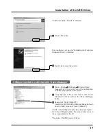
Page 16: ...ge 10 When a USB cable is connected it is recognized as a new hardware and a message is indicated Setup Wizard will start 1 Click on this button Install Hardware Device Drivers is indicated 2 Choose this item 3 Click on this button Locate Driver Files is indicated 4 Choose CD ROM drives 5 Click on this button Installation of the USB Driver Install USB Driver In case of Windows 2000 ...

Page 17: ...perties of the system 2 The properties of the system opens click on the Hardware tab Then click on the Device Manager button 3 Double click Ports COM LPT Confirm that MATSUSHITAUSB Serial Bridge for Touch Panel COMx is found in Ports COM LPT COMx is the COM port number for using a touch panel As for the COM port number the setup number varies in the use environment of the PC The setup of the USB d...

Page 18: ...st PC is started and then Windows is started The CD ROM with USB driver software is inserted into the CD ROM drive Next touch panel and PC are connected with a USB cable see page 10 When a USB cable is connected the wizard of the driver setup starts 1 Click on this button A driver file is copied and set up Setup is completed when all the files of the driver are copied 3 Click on the Finish button ...

Page 19: ...click on the Device Manager button 3 Double click Ports COM LPT Confirm that MATSUSHITA USB Serial Bridge for Touch Panel COMx is found in Ports COM LPT COMx is the COM port number for using a touch panel As for the COM port number the setup number varies in the use environment of the PC The setup of the USB driver is finished Installation of the USB Driver COM port number is confirmed with Device...

Page 20: ...nnected to the PC However it is recognized as a new hardware and a setup wizard is indicated when it is connected to a port which is different from the USB port which did the setup of the driver In this case cancel the setup and connect it to the USB port where the driver was setup If you unplug and plug USB cable quickly the PC sometimes does not recognize it In that case please reboot PC If runn...

Page 21: ...art Run 2 In the Name field input D English Win9x_me setup exe or D English Win2k_xp setup exe Input the applicable file name for the OS you are using 3 Click the OK button The setup program will start 1 Click this button to continue 2 Click to start In the default it is registered as the startup program The driver software will start up automatically the next time the unit is turned on 3 Click to...

Page 22: ...Setup Program Simultaneously hold down the Ctrl Alt Delete keys In the confirmation display that appears select both tpdrv and tpmenu and stop them by clicking on End Task Then proceed to uninstall the Setup Program Note You cannot delete the program using Uninstall if the driver is still running You must stop the driver program first This may be achieved using one of the following two methods In ...

Page 23: ...ed to the driver software in operation when closing the window Pressing the Close button after completion of all settings records all set values in tpdrv ini Setup of a basic Screen see page 24 Calibration Screen Target is displayed in the order of upper left buttom left and upper right And calibration is completed Cursor Position Fine Adjustment As the result of carrying out calibration the mouse...

Page 24: ...the COM port of connecting PC The port being used for connection with the touch panel is selected Setup program When Auto connect is chosen driver software detects it automatically and it is set up If it isn t possible to connect automatically choose a connecting port Connecting port number will vary depending upon the environment of PC Setup of basic settings ...

Page 25: ...ess of the ID number the signal is accepted 2 ID No 1 4 Only the signal of the optional touch pen with the same ID is accepted Screen indication is changed in accordance with the established direction of the panel orientation 1 Normal It is chosen when the display is used in a horizontal position 2 Vertical It is chosen when the display is used in a vertical position when the application software ...

Page 26: ...arget displayed on the screen in order as they appear Target is displayed in the order of upper left bottom left and upper right To stop calibration press any key on the keyboard Once calibration is carried out the calibrated value is saved in the setting file Since the calibrated value is read from the setting file at the time of the next startup there is no need to carry out calibration again Ca...

Page 27: ...ance between the first and the second touches it can be recognized as double click When it is set up Wide it becomes wide and when it is set up Narrow it becomes narrow When compared to Normal setting Touch Pen Switch Sets the function switch of the optional touch pen TY TPEN6 Right Button By touching a display while pushing the function switch it works the same as a right mouse button Off The fun...

Page 28: ...e touch panel click event occurs The cursor does not follow the movement of the finger i e drag function not available Click on touch Releasing the finger from the touch panel click event occurs While the finger touches the touch panel no click event occurs In addition the cursor does not follow the movement of the finger i e no drag function is available Click on Release1 Releasing the finger fro...

Page 29: ...re caution because they produce the most infrared light Keep such light sources as far away as possible from the touch panel Check for incorrect operation due to electrical noise The microcomputer in the Touch Panel may operate incorrectly if any sources of electrical noise are close to it Keep such sources of electrical noise as far away as possible from the Touch Panel Check for incorrect operat...

Page 30: ... 1 2 0 mm 2 0 mm 0 08 0 08 Coordinate output 230 130 elements 276 156 elements 4 0 mm 4 0 mm 0 16 0 16 6 0 mm 6 0 mm 0 24 0 24 Initial touch 30 ms frame max during movement 8 ms frame max Infrared system When operating 0 C 32 F to 50 C 122 F temperature gradient 25 C 77 F hr max 2 When not operating 10 C 14 F to 60 C 140 F temperature gradient 25 C 77 F hr max When operating 20 to 85 must be no co...

Page 31: ...S Unit mm Inch Unit mm Inch 68 75 2 7 928 5 36 6 800 31 5 133 5 2 36 5 1 4 634 25 0 526 5 20 7 53 75 2 1 53 75 2 1 24 5 1 0 69 2 7 8 133 5 2 1066 41 9 748 29 4 632 24 9 58 2 3 58 2 3 1118 44 0 1256 49 4 69 2 7 800 31 5 228 9 0 36 5 1 4 24 5 1 0 8 0 3 228 9 0 68 75 2 7 69 2 7 69 2 7 ...

Page 32: ... as a permanent record of your purchase to aid in identification in the event of theft or loss and for Warranty Service purposes Warranty conditions are managed by distributors to meet the standards set by each country For details contact your dealer where you made your purchase Model Number Serial Number Matsushita Electric Industrial Co Ltd Web Site http www panasonic co jp global Printed in Jap...

Reviews: