background image

2 Prevention of Electrostatic Discharge (ESD) to

Electrostatically Sensitive (ES) Devices

Some semiconductor (solid state) devices can be damaged easily by static electricity. Such components commonly are called
Electrostatically Sensitive (ES) Devices. Examples of typical ES devices are integrated circuits and some field-effect transistors and
semiconductor "chip" components. The following techniques should be used to help reduce the incidence of component damage
caused by electrostatic discharge (ESD).

 1. Immediately before handling any semiconductor component or semiconductor-equipped assembly, drain off any ESD on your

body by touching a known earth ground. Alternatively, obtain and wear a commercially available discharging ESD wrist strap,
which should be removed for potential shock reasons prior to applying power to the unit under test.

 2. After removing an electrical assembly equipped with ES devices, place the assembly on a conductive surface such as alminum

foil, to prevent electrostatic charge buildup or exposure of the assembly.

 3. Use only a grounded-tip soldering iron to solder or unsolder ES devices.

 4. Use only an anti-static solder removal device. Some solder removal devices not classified as "anti-static (ESD protected)" can

generate electrical charge sufficient to damage ES devices.

 5. Do not use freon-propelled chemicals. These can generate electrical charges sufficient to damage ES devices.

 6. Do not remove a replacement ES device from its protective package until immediately before you are ready to install it. (Most

replacement ES devices are packaged with leads electrically shorted together by conductive foam, alminum foil or comparable
conductive material).

 7. Immediately before removing the protective material from the leads of a replacement ES device, touch the protective material

to the chassis or circuit assembly into which the device will be installed.

Caution

Be sure no power is applied to the chassis or circuit, and observe all other safety precautions.

 8. Minimize bodily motions when handling unpackaged replacement ES devices. (Otherwise hamless motion such as the brushing

together of your clothes fabric or the lifting of your foot from a carpeted floor can generate static electricity (ESD) sufficient to
damage an ES device).

3

TY-FB10HMD / TY-FB10HMDC

Summary of Contents for TY-FB10HMD - Monitor Terminal Expansion Board

Page 1: ...hts reserved Unauthorized copying and distribution is a violation of law TY FB10HMD TY FB10HMDC 7 3 HHH Board 2 of 2 Block Diagram 11 7 4 HHH Board 1 of 4 Schematic Diagram 12 7 5 HHH Board 2 of 4 Schematic Diagram 13 7 6 HHH Board 3 of 4 Schematic Diagram 14 7 7 HHH Board 4 of 4 Schematic Diagram 15 8 Exploded Views Replacement Parts List 17 8 1 Parts Location 1 17 8 2 Parts Location 2 18 8 3 Rep...

Page 2: ...d AC plug and each exposed metallic cabinet part on the equipment such as screwheads connectors control shafts etc When the exposed metallic part has a return path to the chassis the reading should be between 1MW and 5 2MW When the exposed metal does not have a return path to the chassis the reading must be Figure 1 1 1 2 Leakage Current Hot Check See Figure 1 1 Plug the AC cord directly into the ...

Page 3: ...Use only a grounded tip soldering iron to solder or unsolder ES devices 4 Use only an anti static solder removal device Some solder removal devices not classified as anti static ESD protected can generate electrical charge sufficient to damage ES devices 5 Do not use freon propelled chemicals These can generate electrical charges sufficient to damage ES devices 6 Do not remove a replacement ES dev...

Page 4: ...a higher melting point than standard solder Typically the melting point is 50 70 F 30 40 C higher Please use a high temperature soldering iron and set it to 700 20 F 370 10 C Pb free solder will tend to splash when heated too high about 1100 F or 600 C If you must use Pb solder please completely remove all of the Pb free solder on the pins or solder area before applying Pb solder If this is not pr...

Page 5: ...4 Replacement 5 TY FB10HMD TY FB10HMDC ...

Page 6: ...5 Connection 6 TY FB10HMD TY FB10HMDC ...

Page 7: ...C541 C542 C543 C544 C350 C545 C351 R329 IC321 C546 C352 C547 C355 R521 R522 D332 C357 D333 C358 R524 IC328 D334 R331 C359 IC329 R526 R333 D337 R334 R528 R529 C360 IC330 C361 R339 C363 C364 R530 R531 IC335 R532 R533 C368 R534 R535 C369 R341 IC339 R342 R536 R537 R344 R538 R345 R346 C370 IC342 C372 IC344 R540 R350 R351 R546 R549 R356 R357 C380 C381 C382 C383 R550 R551 R552 R553 C387 R554 R555 R556 R5...

Page 8: ...21 D302 D303 D304 D305 R301 Q325 R302 D306 Q326 R303 D307 D308 R304 D309 R307 R308 C524 IC301 R309 C331 C332 IC302 D310 C334 D311 R501 D312 IC306 C336 IC307 D313 D314 R310 D315 R311 D316 R312 R313 D317 R314 R315 D319 R316 R317 R318 C340 IC310 C341 R319 IC311 C342 IC312 C343 C344 IC314 D320 R510 R511 C346 D322 R512 C347 D323 R513 R320 D324 R514 R321 D325 IC319 D326 R322 R516 R323 D327 R324 D328 R51...

Page 9: ...7 1 Schematic Diagram Notes 7 Block and Schematic Diagram TY FB10HMD TY FB10HMDC 9 ...

Page 10: ...CLA 5 5 44 SCLA 6 2 5V SDA D1 SDA EEPROM 2 5V 3 3V D0 6 CLKG IC3324 D1 43 IC3302 SCLB D2G SDA D0 8 SDA SDAB CLK 8 40 SDAB VCC 6 D1 D2G SDAB 5V 3 3V 7 MUTE_OUT 77 X3301 XTAL1 XTAL 96 97 DSDA1 INV B EDID B For HD E0 1 IC3301 VCC 5 1 SDA 6 7 E0 WC For FHD 8 EEPROM SCL EDID B HDMI A EDID A EEPROM For HD 1 OE1 4 5 2 VCC IN A OUT_Y IC3326 BUFFER OUT_Y BUFFER IN_A IC3334 VCC 2 4 5 EEPROM Q3307 D S G 3 3V...

Page 11: ...V 9V 5VSTB 5VSTB LVDS_TX8 LVDS_TX8 LVDS_TX6 LVDS_TX6 LVDS_TX7 LVDS_TX7 LVDS_TX5 LVDS_TX5 LVDS_TX3 LVDS_TX2 LVDS_TX0 LVDS_TX3 LVDS_TX0 LVDS_TX1 LVDS_TX4 LVDS_TX4 LVDS_TX1 LVDS_TX2 LVDS_TXC LVDS_TXC CONFIG_DONE nCE 15V 3 3V TP3334 IC3344 VDD 6 VOUT 1 2 5V 3 3VREG 2 5V 1 2V 4 1 2V OUT IC3342 2 VCC VCCI01 03 04 SYG_TYPE3 RESERVE1 RESERVE6 FPGA_RST N_FHD Y2 Y9 UV2 UV9 DP_CLK VS HS DE HDMI_5V_DET1 HDMI_...

Page 12: ...IC3328 1 NC 2 IN A 3 GND 5 VCC 4 OUT Y 4V_B C3323 1u 10V R3617 33 L3303 J0JHC0000078 R3378 22 R3332 4 7k D3313 EZAEG2A50AX C3506 0 1u 16V TP3317 D3323 EZAEG2A50AX C3365 16V 47u C3370 0 1u 16V C3347 15p 50V C3334 0 1u 16V R3311 2 2 R3329 10k C3331 0 1u 16V 3 3VREG 5V D3327 B0HCMM000014 C3301 0 1u 16V Q3301 2SD0601ASL C3313 10V 1u R3350 10k C3357 0 1u 16V R3394 1 8k 4V_B C3341 0 1u 16V L3310 J0JHC00...

Page 13: ...4 PA4 25 PA3 26 PA2 27 PA1 IRQ1 28 PA0 29 P45 30 P46 31 IVDD 32 VDD 33 P60 SBO0A 34 P61 SBT0A 35 P62 SBI0A 36 P05 IRQ6 37 P06 IRQ7 38 P07 IRQ8 39 P70 SDA0 40 P71 SCL0 41 N C 42 N C 43 N C 44 N C 45 P50 RMIN IRQ0 46 P20 47 P21 48 P22 49 P23 50 IVDD 51 VSS 52 P10 53 P11 54 P12 55 P13 56 P14 57 P15 58 P16 59 P17 60 N C 61 N C 62 N C 63 P72 SDA1 64 P73 SCL1 65 P76 CEC0 66 P65 SBO2 67 P66 SBI2 68 P30 6...

Page 14: ...V 3 3VREG L3359 J0JHC0000075 TP3347 EYF6CU IC3341 C6 IO IC3341 P8 GND IC3341 N12 IO IC3341 B5 IO C3509 68u 4V IC3341 A5 IO IC3341 B13 IO R3581 47k C3403 10u 6 3V IC3341 J5 nCONFIG R3644 10k C3402 1u 10V IC3341 D9 IO IC3341 A3 IO R3600 169 1 IC3341 D6 IO R3620 10k IC3341 H7 VCCINT C3408 0 1u 16V IC3341 P14 IO R3582 47k L3321 G1C2R2ZA0083 R3486 10k C3463 10p 50V IC3341 E3 IO C3433 10u 25V R3607 120 ...

Page 15: ...16V 47u TP3326 R3552 10k R3550 22 IC3321 C0JBAZ000801 1 A0 2 A1 3 A2 4 P0 5 P1 6 P2 7 P3 8 GND 9 P4 10 P5 11 P6 12 P7 13 VDAC 14 SCL 1 15 SDA 1 16 VCC R3555 22 C3483 2 2u 25V R3549 10k TP3330 C3478 25V 47u R3546 100 H1 A1 A2 A3 A4 A5 A6 A7 A8 A9 A10 A11 A12 A13 A14 A15 A16 A17 A18 A19 A20 A21 A22 A23 A24 A25 A26 A27 A28 A29 A30 A31 A32 A33 A34 A35 A36 A37 A38 A39 A40 B1 B2 B3 B4 B5 B6 B7 B8 B9 B10...

Page 16: ...TY FB10HMD TY FB10HMDC 16 ...

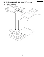
Page 17: ...8 Exploded Views Replacement Parts List 8 1 Parts Location 1 17 TY FB10HMD TY FB10HMDC ...

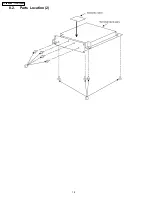
Page 18: ...8 2 Parts Location 2 18 TY FB10HMD TY FB10HMDC ...

Page 19: ...8 3 Replacement Parts List Notes 19 TY FB10HMD TY FB10HMDC ...

Page 20: ...SEET 1 8 XZBT6506 POLY BAG 1 9 THEL0239 SCREW 4 10 TQE6691 POLY BAG 1 TY FB10HMDC Ref No Part No Part Name Description Pcs Remarks 1 THEL027N SCREW 8 2 TPCB13165 CARTON BOX 1 3 TPDF1103 CUSHION 1 4 TPEH135 PROTECT COVER 1 5 TBMU803 TERAMINAL SHEET 1 6 TQZH886 INSTRUCTION SEET 1 7 TQZH915 INSTRUCTION SEET 1 8 XZBT6506 POLY BAG 1 9 THEL0239 SCREW 4 10 TQE6691 POLY BAG 1 8 4 Mechanical Replacement Pa...

Page 21: ...4 C 0 010UF K 16V 3 C3412 1 3 F1G1C104A077 C 0 10UF K 16V 2 Ref No Part No Part Name Description Pcs Remarks C3414 F1J0J1060004 C 0 010UF K 16V 1 C3415 F1G1C104A077 C 0 10UF K 16V 1 C3416 20 F1J0J1060004 C 0 010UF K 16V 5 C3421 F1G1C104A077 C 0 10UF K 16V 1 C3422 F1J0J1060004 C 0 010UF K 16V 1 C3423 25 F1G1C104A077 C 0 10UF K 16V 3 C3426 F1J0J1060004 C 0 010UF K 16V 1 C3427 F1G1C104A077 C 0 10UF K...

Page 22: ... INDUCTOR 3 L3328 J0JHC0000078 CHIP INDUCTOR 1 L3329 J0JCC0000241 CHIP INDUCTOR 1 L3343 4 4 J0JCC0000241 CHIP INDUCTOR 2 L3345 55 J0MAB0000201 LC FILTER 11 L3357 60 J0JCC0000241 CHIP INDUCTOR 4 PCB TXNHHH10XXT CIRCUIT BOARD HHH 1 Q3301 04 2SD0601ARL TRANSISTOR 4 Q3307 0 8 2SK1228 FET 2 Q3312 2SD0601ARL TRANSISTOR 1 Q3313 2SA207700L TRANSISTOR 1 Q3314 1 5 2SD0601ARL TRANSISTOR 2 Q3321 2SD0601ARL TR...

Page 23: ...08 ERJ3EKF1002 M 10KOHM 1 16W 1 R3509 D0GB473JA057 M 47KOHM J 1 16W 1 R3510 EXB2HV473JV RESISTOR ARRAY 1 R3511 1 2 D0GB473JA057 M 47KOHM J 1 16W 2 Ref No Part No Part Name Description Pcs Remarks R3513 D0GB103JA057 M 10KOHM J 1 16W 1 R3514 D0GB473JA057 M 47KOHM J 1 16W 1 R3515 D0GB103JA057 M 10KOHM J 1 16W 1 R3516 D0GB473JA057 M 47KOHM J 1 16W 1 R3517 ERJ3GEYJ100 M 10 OHM J 1 16W 1 R3518 D0GB473JA...

Page 24: ...J 1 16W 2 R3626 ERJ3EKF1690 M 169 OHM 1 16W 1 R3627 2 8 ERJ3EKF1200 M 120 OHM 1 16W 2 R3629 ERJ3EKF1690 M 169 OHM 1 16W 1 R3630 3 1 ERJ3EKF1200 M 120 OHM 1 16W 2 R3632 ERJ3EKF1690 M 169 OHM 1 16W 1 R3633 3 4 ERJ3EKF1200 M 120 OHM 1 16W 2 R3635 ERJ3EKF1690 M 169 OHM 1 16W 1 R3636 3 7 ERJ3EKF1200 M 120 OHM 1 16W 2 R3638 ERJ3EKF1690 M 169 OHM 1 16W 1 R3639 4 0 ERJ3EKF1200 M 120 OHM 1 16W 2 R3641 44 D...

Reviews: