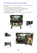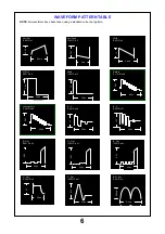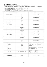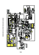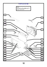
HOW TO MOVE THE CHASSIS INTO SERVICE POSITION
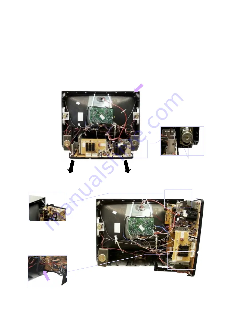
1. Remove the bead clamper from the mains lead and affix, using back cover screw, into top right-hand cabinet rib (A),
shown in Fig.4.
2. Remove 2 screws (B), as shown in Fig.5, and remove speaker assembly.
3. Hold and lift the rear of the chassis and gently pull the chassis toward you, as shown in Fig.4.
4. Release the respective wiring clips and rotate the chassis vertically through 90
°
, anti-clockwise.
5. Locate the base of the chassis frame into location (C), shown in Fig.6 / Fig.8.
6. Clip the chassis frame onto the bead clamper, shown in Fig.6 / Fig.7.
7. After servicing replace the bead clamper and speaker, and ensure all wiring is returned to its original position before
returning the receiver to the customer.
Fig.4.
Fig.5.
Fig.6.
4
(A)
Fig.7.
Fig.5.
Screws
(B)
Fig.8.
a
(C)
Summary of Contents for TX-32PF10P
Page 8: ...32 5 6833 7 21 2 5 0 1 1 0 1 0 9 1 9 R D U G U R P 7 3 3 0 7 3 3 0 0 ...
Page 29: ......
Page 30: ......
Page 31: ......
Page 32: ......
Page 33: ......
Page 34: ......
Page 35: ......
Page 36: ......
Page 37: ......
Page 38: ......
Page 45: ...M BOARD TNP8EM018 DIODE S D1012 A1 D1013 A1 D1014 B1 D1015 B1 D1016 B1 D1017 B1 42 1 2 A B C ...
Page 46: ...N BOARD TNP8EN017 TRAN S Q1011 D4 Q1012 D6 I C S IC1011 E6 1 2 3 4 5 6 7 A B C D E ...


