background image

CONTENTS

SAFETY PRECAUTIONS..........................................................................................................................................................2

SERVICE HINTS .......................................................................................................................................................................3

SERVICE POSITION.................................................................................................................................................................4

ADJUSTMENT PROCEDURE AND SELF-CHECK ..................................................................................................................5

WAVEFORM PATTERN TABLE ...............................................................................................................................................6

ALIGNMENT SETTINGS...........................................................................................................................................................7

BLOCK DIAGRAMS ..................................................................................................................................................................8

PARTS LOCATION .................................................................................................................................................................12

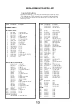
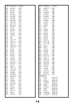
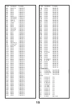
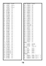
REPLACEMENT PARTS LIST ................................................................................................................................................13

SCHEMATIC DIAGRAMS .......................................................................................................................................................30

CONDUCTOR VIEWS.............................................................................................................................................................39

SAFETY PRECAUTIONS

GENERAL GUIDE LINES

1.  It is advisable to insert an isolation transformer in the

a.c. supply before servicing a hot chassis.

2.  When servicing, observe the original lead dress in the

high voltage circuits. If a short circuit is found, replace
all parts that have been overheated or damaged by
the short circuit.

3.  After servicing, see that all the protective devices

such as insulation barriers, insulation papers, shields
and isolation R-C combinations are correctly
installed.

4.  When the receiver is not being used for a long period

of time, unplug the power cord from the a.c. outlet.

5.  Potentials as high as 33kV are present when this

receiver is in operation. Operation of the receiver
without the rear cover involves the danger of a shock
hazard from the receiver power supply. Servicing
should not be attempted by anyone who is not
familiar with the precautions necessary when working
on high voltage equipment. Always discharge the
anode of the tube.

6.  After servicing make the following leakage current

checks to prevent the customer from being exposed
to shock hazard.

LEAKAGE CURRENT COLD CHECK

1.  Unplug the a.c. cord and connect a jumper between

the two prongs of the plug.

2.  Turn on the receiver’s power switch.
3.  Measure the resistance value with an ohmmeter,

between the jumpered a.c. plug and each exposed
metallic cabinet part on the receiver, such as screw
heads, aerials, connectors, control shafts etc. When
the exposed metallic part has a return path to the
chassis, the reading should be between 4M ohm and
20M ohm. When the exposed metal does not have a
return path to the chassis, the reading must be
infinite.

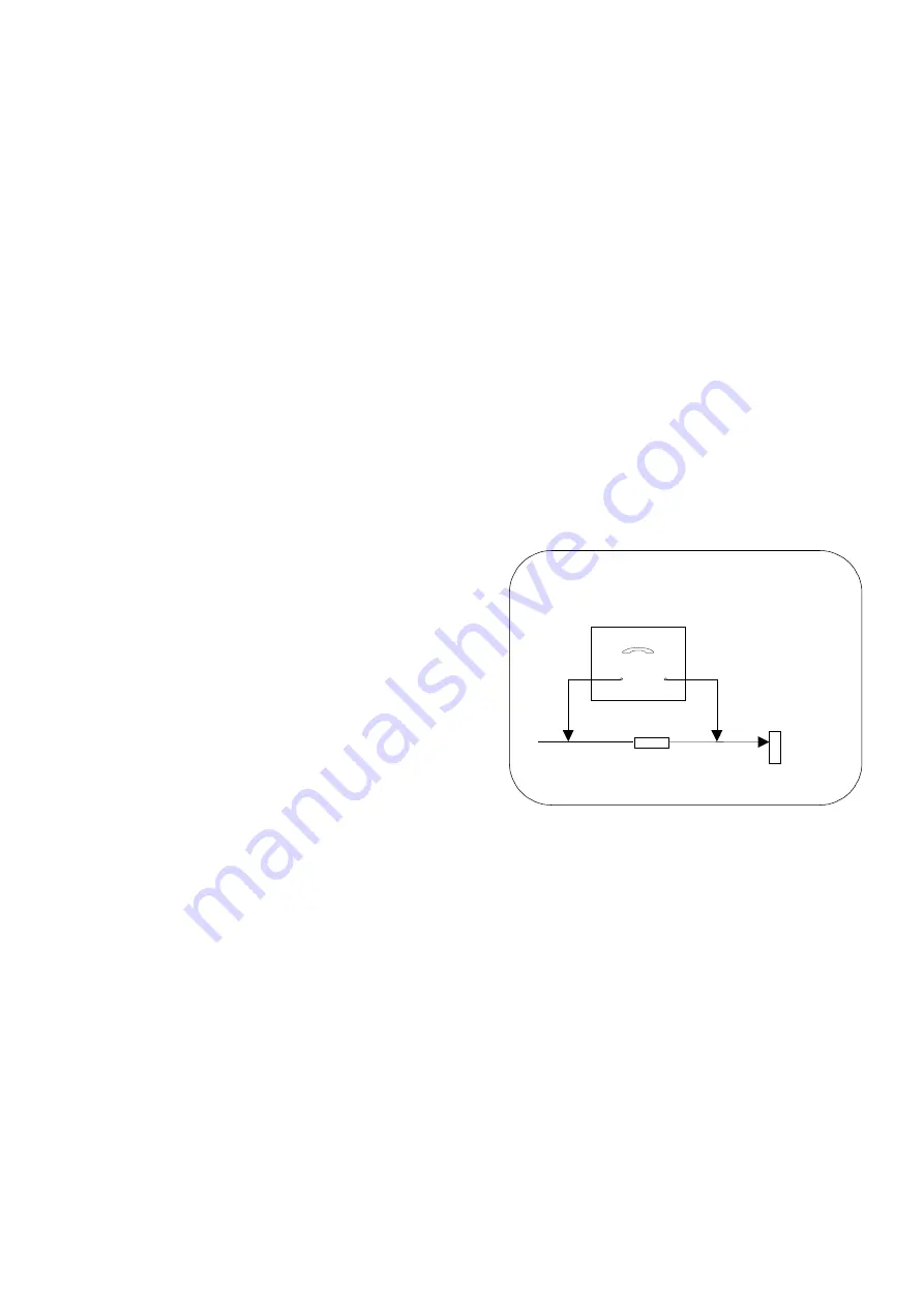
LEAKAGE CURRENT HOT CHECK

1.  Plug the a.c. cord directly into the a.c. outlet. Do not

use an isolation transformer for this check.

2. Connect 

2k

 10W resistor in series with an

exposed metallic part on the receiver and an earth,
such as a water pipe.

3.  Use an a.c. voltmeter with high impedance to

measure the potential across the resistor.

4.  Check each exposed metallic part and check the

voltage at each point.

5.  Reverse the a.c. plug at the outlet and repeat each of

the above measurements.

6.  The potential at any point should not exceed

1,4 Vrms. In case a measurement is outside the limits
specified, there is a possibility of a shock hazard, and
the receiver should be repaired and rechecked before
it is returned to the customer.

X-RADIATION WARNING

1.  The potential sources of X-Radiation in TV sets are

the high voltage section and the picture tube.

2.  When using a picture tube test jig for service, ensure

that the jig is capable of handling 33kV without
causing X-Radiation.

NOTE:

 It is important to use an accurate periodically

calibrated high voltage meter.
1.  Set the brightness to minimum.
2.  Measure the high voltage. The meter should

indicate:- 32kV ± 1kV. If the meter indication is out of
tolerance, immediate service and correction is
required to prevent the possibility of premature
component failure.

3.  To prevent any X-Radiation possibility, it is essential

to use the specified tube.

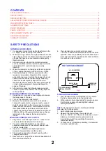
HOT CHECK CIRCUIT

A.C. VOLTMETER

WATER PIPE

(EARTH)

TO INSTRUMENT’S EXPOSED
METALLIC PARTS

Fig. 1.

2k

 10 Watts

2

Summary of Contents for TX-32PF10P

Page 1: ...75Ω Audio 21 pin 500mV rms 1kΩ AV2 IN Video 21 pin 1V p p 75Ω Audio 21 pin 500mV rms 10kΩ S Video IN Y 1V p p 75Ω 21 pin C 0 3V p p 75Ω AV2 OUT Video 21 pin 1V p p 75Ω Audio 21 pin 500mV rms 1kΩ Selectable Output 21 pin AV3 IN S Video IN Y 1V p p 75Ω 4 pin C 0 3V p p 75Ω Audio RCAx2 500mV rms10kΩ Video RCAx1 1V p p 75Ω AV4 IN Video 21 pin 1V p p 75Ω Audio 21 pin 500mV rms 10kΩ S Video IN Y 1V p p ...

Page 2: ...cabinet part on the receiver such as screw heads aerials connectors control shafts etc When the exposed metallic part has a return path to the chassis the reading should be between 4M ohm and 20M ohm When the exposed metal does not have a return path to the chassis the reading must be infinite LEAKAGE CURRENT HOT CHECK 1 Plug the a c cord directly into the a c outlet Do not use an isolation transf...

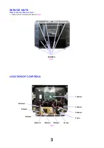
Page 3: ...ICE HINTS How to remove the rear cover 1 Remove the 10 screws as shown in Fig 2 LOCATION OF CONTROLS M Board 3 SCREWS Fig 2 Fig 3 Y Board V Board N Board D Board H Board E Board G Board F Board Screen Focus ...

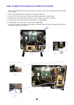
Page 4: ... the chassis toward you as shown in Fig 4 4 Release the respective wiring clips and rotate the chassis vertically through 90 anti clockwise 5 Locate the base of the chassis frame into location C shown in Fig 6 Fig 8 6 Clip the chassis frame onto the bead clamper shown in Fig 6 Fig 7 7 After servicing replace the bead clamper and speaker and ensure all wiring is returned to its original position be...

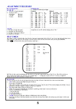
Page 5: ... Self Check is also used to automatically check the bus lines and hexadecimal code of the TV set If the CCU ports have been checked and found to be incorrect or not located then will appear in place of O K For more in depth TV diagnostics use the LUCI interface as listed below Service Aids To aid in the service of our current chassis there are a number of Service Aids which have been made availabl...

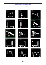
Page 6: ...in 41 2 2V 32µs Vert Drive IC451 Pin 2 8ms 63V Vert Out IC601 Pin 1 8 6ms 0 6V VFLB IC451 Pin 5 1V 8 6ms Video In IC1101 Pin 68 0 9V 64µs H Out IC601 Pin 8 3 9V 32µs HFLB IC601 Pin 13 32µs 7V 32µs 1V R Y IC601 Pin 26 Luminance In IC601 Pin 28 0 9V 32µs B Y IC601 Pin 27 32µs 1 3V 28µs 6V H Out IC3901 Pin 3 V Out IC3901 Pin 21 0 1V 32µs E W Out IC601 Pin 3 280mV 8 5ms ...

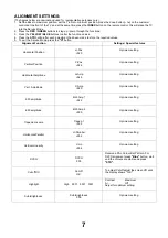
Page 7: ...ton Alignment Function Settings Special features Horizontal Position H Pos 020 Optimum setting Vertical Position V Pos 024 Optimum setting Horizontal Amplitude H Amp 049 Optimum setting Vert Amplitude V Amp 029 Optimum setting EW amplitude E W Amp1 022 Optimum setting EW amplitude E W Amp2 000 Optimum setting Trapezium comp Trapez 1 033 Optimum setting Horizontal Parallel H Parallel 032 Optimum se...

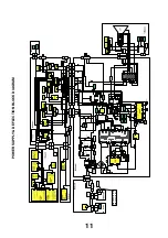
Page 8: ...32 5 6833 7 21 2 5 0 1 1 0 1 0 9 1 9 R D U G U R P 7 3 3 0 7 3 3 0 0 ...

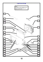
Page 9: ...ARTS LOCATION 12 NOTE The numbers on the exploded view below refer to the mechanical section of the Replacement Parts List 17 4 30 2 6 1 18 19 5 9 28 25 16 27 29 14 15 3 22 24 10 26 20 7 8 11 12 21 23 13 ...

Page 10: ...CK UM 3DJ 2P RELAY RL801 TSE1885 1 THERMISTOR R805 232266296706 FIX CLIP SOD1 31221212478 FIX CLIP SOD9 31221212478 INSTRUCTION BOOKS BULG ROMANIAN TQB8E2700MN2 POLISH HUNG TQB8E2700PQ2 CZECH ENGLISH TQB8E2700RU2 I C s AUDIO OUTPUT IC251 LA4282 AUDIO AMPLIFIER IC281 TDA2030AV RGB OUTPUT IC351 TDA6111Q N4 RGB OUTPUT IC361 TDA6111Q N4 RGB OUTPUT IC371 TDA6111Q N4 REGULATOR IC381 TL431ACLPM VERTICAL ...

Page 11: ...DE D847 ERA15 01V3 DIODE D848 EU02 DIODE D849 FMGG26S DIODE D850 ERB32 02E DIODE D851 FMGG2CSLF116 DIODE D852 MA4062 DIODE D853 1N4150T 77 DIODE D854 ERA15 01V3 DIODE D855 D10SC6MRL DIODE D856 MA165TA5 DIODE D857 FML22SLF610 DIODE D860 1SS254T 77 DIODE D861 MTZJT 775 1C DIODE D901 1SS254T 77 DIODE D902 1SS254T 77 DIODE D903 1SS254T 77 DIODE D910 R2KNLFA1 DIODE D1011 LN81RPHL DIODE D1102 MA4051 DIO...

Page 12: ...OR Q1665 BC847B TRANSISTOR Q1666 BC847B TRANSISTOR Q1667 BC847B TRANSISTOR Q1801 BC847B TRANSISTOR Q1802 BC847B TRANSISTOR Q1803 BC847B TRANSISTOR Q1804 BC857B TRANSISTOR Q1805 BC857B TRANSISTOR Q1806 BC857B TRANSISTOR Q1901 BC847B TRANSISTOR Q2101 BC860B TRANSISTOR Q2102 BC860B TRANSISTOR Q2103 BC860B TRANSISTOR Q2301 BC847B TRANSISTOR Q2302 BC847B TRANSISTOR Q2305 BC857B TRANSISTOR Q2307 BC860B ...

Page 13: ...CELDR35V COIL L1532 EXCELDR35V COIL L1533 EXCELDR35V COIL L1534 EXCELDR35V COIL L1535 EXCELDR35V COIL L1536 EXCELDR35V COIL L1537 TLT100K991R COIL L1538 TLT018K991R COIL L1539 TLT033K991R COIL L1540 TLT018K991R COIL L1541 TLT033K991R COIL L1542 TLT018K991R COIL L1543 TLT033K991R COIL L1802 EXCELDR35V COIL L1803 EXCELDR35V COIL L1807 EXCELDR35V COIL L1808 TLT470K991R COIL L1809 EXCELDR35V COIL L181...

Page 14: ... M CARB JSF017 ERJ6GEY0R00 0 1W 5 0 S M CARB JSF029 ERJ6GEY0R00 0 1W 5 0 S M CARB JSF028 ERJ6GEY0R00 0 1W 5 0 S M CARB JSF027 ERJ6GEY0R00 0 1W 5 0 S M CARB JSF026 ERJ6GEY0R00 0 1W 5 0 S M CARB JSF025 ERJ6GEY0R00 0 1W 5 0 S M CARB JSF024 ERJ6GEY0R00 0 1W 5 0 S M CARB JSF023 ERJ6GEY0R00 0 1W 5 0 S M CARB JSF022 ERJ6GEY0R00 0 1W 5 0 S M CARB JSF021 ERJ6GEY0R00 0 1W 5 0 S M CARB JSF020 ERJ6GEY0R00 0 1...

Page 15: ...1 3W 5 820 METAL R574 ERG3FJ151 3W 5 150 S M CARB R579 ERJ6GEYJ274 0 1W 5 270K S M CARB R580 ERJ6GEYJ563 0 1W 5 56K S M CARB R581 ERJ6GEYJ104 0 1W 5 100K S M CARB R582 ERJ6GEYJ225 0 1W 5 2M2 S M CARB R583 ERJ6GEYJ225 0 1W 5 2M2 S M CARB R588 ERJ6GEY0R00 0 1W 5 0 S M CARB R601 ERJ6GEYJ153 0 1W 5 15K S M CARB R613 ERJ6GEYJ101 0 1W 5 100 S M CARB R614 ERJ6GEYJ101 0 1W 5 100 S M CARB R615 ERJ6GEYJ101 ...

Page 16: ...ARB R917 ERJ6GEYJ121 0 1W 5 120 FUSIBLE R919 ERQ14AJW390 0 25W 5 39 FUSIBLE R920 ERQ14AJW390 0 25W 5 39 CARBON R922 ERD25TJ683 0 25W 5 68K CARBON R923 ERD25TJ683 0 25W 5 68K CARBON R924 ERDS1FYJ330 0 5W 5 33 S M CARB R925 ERJ6GEY0R00 0 1W 5 0 S M CARB R926 ERJ6GEY0R00 0 1W 5 0 CARBON R927 ERD25TJ122 0 25W 5 1K2 CARBON R928 ERD25TJ5R6 0 25W 5 5R6 CARBON R929 ERDS1FYJ471 0 5W 5 470 CARBON R931 ERDS1...

Page 17: ... CARB R1515 ERJ6GEYJ101 0 1W 5 100 S M CARB R1517 ERJ6GEYJ180 0 1W 5 18 S M CARB R1518 ERJ6GEYJ180 0 1W 5 18 S M CARB R1519 ERJ6GEYJ561 0 1W 5 560 S M CARB R1520 ERJ6GEYJ471 0 1W 5 470 S M CARB R1521 ERJ6GEYJ820 0 1W 5 82 S M CARB R1522 ERJ6GEYJ103 0 1W 5 10K S M CARB R1523 ERJ6GEYJ390 0 1W 5 39 S M CARB R1524 ERJ6GEYJ560 0 1W 5 56 S M CARB R1525 ERJ6GEYJ271 0 1W 5 270 S M CARB R1526 ERJ6GEY0R00 0...

Page 18: ...RB R1673 ERJ6GEY0R00 0 1W 5 0 S M CARB R1674 ERJ6GEY0R00 0 1W 5 0 S M CARB R1675 ERJ6GEY0R00 0 1W 5 0 S M CARB R1676 ERJ6GEYJ560 0 1W 5 56 S M CAR R1677 ERJ6ENF6800 0 1W 5 80 S M CAR R1678 ERJ6ENF1500 0 1W 5 15 S M CAR R1679 ERJ6ENF1500 0 1W 5 15 S M CARB R1680 ERJ6GEYJ271 0 1W 5 270 S M CARB R1681 ERJ6GEYJ271 0 1W 5 270 S M CARB R1682 ERJ6GEYJ271 0 1W 5 270 S M CARB R1683 ERJ6GEYJ271 0 1W 5 270 S...

Page 19: ...72 ERJ6GEYJ562 0 1W 5 5K6 S M CARB R2373 ERJ6GEYJ562 0 1W 5 5K6 S M CARB R2376 ERJ6GEYJ103 0 1W 5 10K S M CARB R2377 ERJ6GEYJ103 0 1W 5 10K S M CARB R2459 ERJ6GEY0R00 0 1W 5 0 S M CARB R2460 ERJ6GEY0R00 0 1W 5 0 S M CARB R2474 ERJ6GEYJ101 0 1W 5 100 S M CARB R2475 ERJ6GEYJ101 0 1W 5 100 S M CARB R3004 ERJ6GEYJ470 0 1W 5 47 S M CARB R3005 ERJ6GEYJ104 0 1W 5 100K S M CARB R3006 ERJ6GEYJ221 0 1W 5 22...

Page 20: ...0 0 1W 5 10 S M CARB R3430 ERJ6GEYJ103 0 1W 5 10K S M CARB R3431 ERJ6GEYJ101 0 1W 5 100 S M CARB R3432 ERJ6GEYJ221 0 1W 5 220 S M CARB R3433 ERJ6GEYJ332 0 1W 5 3K3 S M CARB R3434 ERJ6GEYJ333 0 1W 5 33K S M CARB R3435 ERJ6GEYJ680 0 1W 5 68 S M CARB R3436 ERJ6GEYJ102 0 1W 5 1K S M CARB R3437 ERJ6GEYJ102 0 1W 5 1K S M CARB R3438 ERJ6GEYJ101 0 1W 5 100 S M CARB R3439 ERJ6GEYJ333 0 1W 5 33K S M CARB R3...

Page 21: ... ELECT C282 ECA1HM010GB 50V 1µF ELECT C283 ECJ2VF1H223Z 350V 22nF S M CAP C284 ECUV1H102KBX 50V 1nF ELECT C285 ECA1HM010GB 50V 1µF ELECT C287 ECA1HM100GB 50V 10µF ELECT C288 ECA1HM010GB 50V 1µF S M CAP C289 ECUV1H103KBX 50V 10nF FILM C290 ECQM1H474J 50V 470nF ELECT C291 ECA1VM102GB 35V 1nF FILM C292 ECQM1H474J 50V 470nF S M CAP C293 ECUV1H102JCX 50V 1nF ELECT C295 ECA50YT2R2KB 50V 1nF ELECT C296 E...

Page 22: ... C849 ECKC2H391J 500V 390pF CERAMIC C852 ECKC3D102J 2KV 1nF ELECT C853 ECEA1CU332 16V 3300µF ELECT C854 ECA1EM221GB 25V 220pF ELECT C856 ECA1EM222GB 25V 2200µF ELECT C857 ECA1EM471GB 25V 470µF ELECT C858 ECOS2EA271BB 250V 270µF CERAMIC C859 ECKC2H471J 500V 470pF ELECT C861 ECOS2EA221AB 250V 220µF ELECT C863 ECA1EM332E 25V 3300µF ELECT C864 ECA0JM102GB 6 3V 1000µF ELECT C866 ECA1HM101GB 50V 100µF E...

Page 23: ... M CAP C1574 ECUV1H104ZFX 50V 100nF S M CAP C1575 ECUV1H104ZFX 50V 100nF S M CAP C1576 ECUV1H104ZFX 50V 100nF S M CAP C1577 ECUV1H104ZFX 50V 100nF S M CAP C1578 ECUV1H104ZFX 50V 100nF S M CAP C1579 ECUV1H104ZFX 50V 100nF S M CAP C1580 ECUV1H104ZFX 50V 100nF S M CAP C1581 ECUV1H104ZFX 50V 100nF S M CAP C1582 ECUV1H104ZFX 50V 100nF S M CAP C1583 ECUV1H104ZFX 50V 100nF S M CAP C1584 ECUV1H104ZFX 50V ...

Page 24: ...LECT C1819 ECA1HM101GB 50V 100µF S M CAP C1820 ECUV1H680JCX 50V 68pF S M CAP C1821 ECUV1H104ZFX 50V 100nF S M CAP C1823 ECUV1H331JCX 50V 330pF S M CAP C1824 ECUV1H104ZFX 50V 100nF S M CAP C1825 ECUV1C104KBX 16V 100nF S M CAP C1826 ECUV1C104KBX 16V 100nF S M CAP C1827 ECUV1C104KBX 16V 100nF S M CAP C1828 ECUV1H150JCX 50V 15pF S M CAP C1829 ECUV1C104KBX 16V 100nF S M CAP C1830 ECUV1C104KBX 16V 100nF...

Page 25: ...2 ECKC1H561J 50V 560pF CERAMIC C3284 ECKC1H561J 50V 560pF ELECT C3351 ECA1CM221GB 16V 220µF ELECT C3401 ECEA1HKA100 50V 10pF S M CAP C3402 ECUV1H561JCX 50V 560pF S M CAP C3403 ECUV1H561JCX 50V 560pF S M CAP C3404 ECUV1H561JCX 50V 560pF S M CAP C3405 ECUV1H561JCX 50V 560pF S M CAP C3406 ECUV1H561JCX 50V 560pF S M CAP C3407 ECUV1H561JCX 50V 560pF S M CAP C3408 ECUV1H561JCX 50V 560pF ELECT C3409 ECEA...

Page 26: ... FS LINK R847 TSF19252 FS LINK R848 TSF19402 FS LINK R1914 TSF19161 SWITCHES SWITCH S840 ESB92S11B SWITCH S1071 EVQPB105K SWITCH S1072 EVQPB105K SWITCH S1073 EVQPB105K SWITCH S1074 EVQPB105K SWITCH S1075 EVQPB105K DIFFERENCES FOR MODEL TX 32PF10P AV COVER TKP8E1253 MECHANICAL PARTS C R T 20 W76LPX555X05 CABINET 21 TTYA0339 2 CENTRE SPEAKER 22 EASG12D123K2 CONTROL BRACKET 23 TMWA002 3 D P C B 24 TN...

Page 27: ...Description Cct Ref Parts Number Description Cct Ref Parts Number ELECT C265 ECA1HM3R3GB 50V 3 3µF ELECT C855 ECEA1HU102 50V 1000µF CERAMIC C2377 ECKC1H102J 50V 1nF CERAMIC C2378 ECKC1H102J 50V 1nF 30 ...

Page 28: ...rinting and are subject to change without notice REMARKS a Do not touch the hot part or the hot and cold parts at the same time as you are liable to a shock hazard b Do not short circuit the hot and cold circuits as electrical components may be damaged c Do not connect an instrument such as an oscilloscope to the hot and cold circuits simultaneously as this may cause fuse failure Connect the earth...

Page 29: ......

Page 30: ......

Page 31: ......

Page 32: ......

Page 33: ......

Page 34: ......

Page 35: ......

Page 36: ......

Page 37: ......

Page 38: ......

Page 39: ...1104 D5 Q1109 A5 D603 D5 IC1105 B6 Q1110 A5 D605 B5 IC1106 D6 Q1111 C5 D607 B5 IC1901 C6 Q1112 E5 D609 B5 IC2101 B3 Q1113 E5 D610 C4 IC2351 A6 Q1114 C6 D611 C4 IC3001 B1 Q1116 C6 D612 C4 IC3801 A2 Q1118 D6 D615 B5 IC3802 C5 Q1901 C6 D616 B5 IC3805 B5 Q2101 B2 D617 D5 IC3806 D1 Q2102 C2 D618 C4 Q2103 B2 D620 B5 T P S Q2301 B2 D651 C4 TPE1 A2 Q2302 A2 D652 C4 TPE2 B3 Q2305 A2 D653 B4 TPE23 D6 Q2307 ...

Page 40: ...2 D1 D808 A4 Q3903 E1 D809 A4 Q3904 D1 D810 A5 Q3905 D2 D812 A4 Q3906 E2 D813 A4 Q3907 E2 D814 B4 Q3908 E2 D815 B4 Q3911 D2 D817 B6 Q3912 E2 D818 A5 Q3916 E1 D819 A4 D820 B4 T P S D821 B4 TPDG1 A1 D845 C7 TPDG2 B1 D846 D7 TPDG11D1 D847 D7 TPDG12E1 D848 D6 TPDG13D1 D849 D6 TPDG14D2 D851 D4 TPDG15E2 D852 C4 D853 E6 I C S D854 D7 IC801 A4 D855 D6 IC845 C4 D856 E7 IC852 E6 D857 E6 IC3901 E1 D858 E5 D8...

Page 41: ...F BOARD TNPA1068 TRAN S Q1663 B2 Q1664 B2 Q1665 B2 Q1666 C1 Q1667 C1 I C S IC1502 B3 IC1503 C3 IC1504 D1 IC1505 D2 IC1506 C2 IC1509 C1 IC1510 C1 1 2 3 A B C D ...

Page 42: ...F BOARD TNPA1068 TRAN S Q1501 D3 Q1502 C3 Q1503 B2 Q1504 C1 Q1505 C1 Q1506 C1 Q1507 C1 Q1508 C1 Q1509 C1 Q1510 D1 Q1511 D1 Q1519 D1 Q1660 C2 Q1661 C2 Q1662 C2 I C S IC1507 B2 1 2 3 A B C D ...

Page 43: ...G BOARD TNPA0877 TRAN S Q1801 C2 Q1802 C2 Q1803 C3 Q1804 B2 Q1805 B3 Q1806 B3 Q2502 B2 Q2505 A2 Q2506 B2 Q2507 A1 I C S IC1801 C2 IC1802 C1 IC2501 B2 DIODE S D1801 B2 D1802 B2 1 2 3 A B C 41 ...

Page 44: ...Q2410 A3 Q2411 A3 Q2412 A3 Q3401 B1 Q3402 C1 Q3403 B1 Q3404 C1 Q3405 C3 Q3406 C3 DIODE S D2401 A2 D2403 A3 D2404 A3 D2405 A3 D2406 A3 D2407 A3 D2408 A3 D3401 C3 D3402 C3 T P S TPH1 D1 TPH2 A2 TPH3 D1 TPH004 D1 TPH005 D1 I C S IC2401 A2 IC2402 A3 1 2 3 A B C D 40 ...

Page 45: ...M BOARD TNP8EM018 DIODE S D1012 A1 D1013 A1 D1014 B1 D1015 B1 D1016 B1 D1017 B1 42 1 2 A B C ...

Page 46: ...N BOARD TNP8EN017 TRAN S Q1011 D4 Q1012 D6 I C S IC1011 E6 1 2 3 4 5 6 7 A B C D E ...

Page 47: ...A2 Q3352 A2 DIODE S D351 B3 D352 B3 D361 A2 D362 A2 D371 C3 D372 C2 D373 C3 D374 A1 D375 B2 D387 B1 D901 C1 D902 C1 D903 C1 D910 C1 D911 D2 D3351 A2 D3352 A3 D3353 A1 D3354 C3 T P S TPY1 B3 TPY2 A2 TPY3 C2 TPKR B3 TPKG B2 TPKB C2 I C S IC351 B2 IC361 A1 IC371 C3 IC381 C3 1 2 3 A B C D 39 ...

Reviews: